NCP5901MNTBG ON Semiconductor, NCP5901MNTBG Datasheet
NCP5901MNTBG
Specifications of NCP5901MNTBG
Available stocks


Related parts for NCP5901MNTBG

NCP5901MNTBG Summary of contents
Page 1
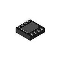
... AJMG AJ = Specific Device Code M = Date Code = Pb−Free Device G ORDERING INFORMATION Device Package NCP5901MNTBG DFN8 (Pb−Free) NCP5901DR2G SOIC−8 (Pb−Free) †For information on tape and reel specifications, including part orientation and tape sizes, please refer to our Tape and Reel Packaging Specification Brochure, BRD8011/D. ...
Page 2
VCC PWM EN Table 1. Pin Descriptions Pin No. Symbol 1 BST Floating bootstrap supply pin for high side gate driver. Connect the bootstrap capacitor between this pin and the SW pin. 2 PWM Control input. The PWM signal has ...
Page 3
CR1 MMSD4148 C4 R164 0.027uF R1 1.02 0.0 NCP5901 TP3 R143 0.0 TP4 BST HG PWM PWM SW DRON EN GND VCC LG PAD TP8 C5 1uF Table 2. ABSOLUTE MAXIMUM RATINGS Pin Symbol VCC BST SW DRVH DRVL ...
Page 4
Table 4. ELECTRICAL CHARACTERISTICS 4.5 V < BST−SWN < 13.2 V, 4.5 V < BST < < SWN < Parameter SUPPLY VOLTAGE VCC Operation Voltage Power ON Reset Threshold UNDERVOLTAGE LOCKOUT VCC Start Threshold ...
Page 5
Table 4. ELECTRICAL CHARACTERISTICS 4.5 V < BST−SWN < 13.2 V, 4.5 V < BST < < SWN < Parameter LOW SIDE DRIVER (VCC = 12 V) Output Impedance, Sourcing Current Output Impedance, Sinking ...
Page 6
PWM DRVH−SW DRVL IL 1V Figure 4. Figure 5. Timing Diagram http://onsemi.com 6 ...
Page 7
... The NCP5901 gate driver is a single phase MOSFET driver designed for driving N−channel MOSFETs in a synchronous buck converter topology. The NCP5901 is designed to work with ON Semiconductor’s NCP6131 multi−phase controller. This gate driver is optimized for desktop applications. Undervoltage Lockout The DRVH and DRVL are held low until V 4 ...
Page 8
... G C SEATING PLANE −Z− 0.25 (0.010 *For additional information on our Pb−Free strategy and soldering details, please download the ON Semiconductor Soldering and Mounting Techniques Reference Manual, SOLDERRM/D. PACKAGE DIMENSIONS SOIC−8 NB CASE 751−07 ISSUE 0.10 (0.004 SOLDERING FOOTPRINT* 1 ...
Page 9
... NOTE 3 0.05 C 0.30 *For additional information on our Pb−Free strategy and soldering details, please download the ON Semiconductor Soldering and Mounting Techniques Reference Manual, SOLDERRM/D. N. American Technical Support: 800−282−9855 Toll Free USA/Canada Europe, Middle East and Africa Technical Support: Phone: 421 33 790 2910 Japan Customer Focus Center Phone: 81− ...