EVAL6599-400W-T STMicroelectronics, EVAL6599-400W-T Datasheet
EVAL6599-400W-T
Specifications of EVAL6599-400W-T
Available stocks


Related parts for EVAL6599-400W-T


EVAL6599-400W-T Summary of contents
Page 1
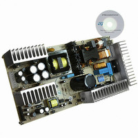
Wide range 400W (+200 V@1 +75 V@1 A) Introduction This note describes the performances of a 400W reference board, with wide-range mains operation and power-factor-correction (PFC) and presents the results of its bench evaluation. The electrical specification refers ...
Page 2
Contents Contents 1 Main characteristics and circuit description . . . . . . . . . . . . . . . . . . . . . 4 2 Electrical test results . . . . . . ...
Page 3
AN2509 List of figures Figure 1. PFC pre-regulator electrical diagram . . . . . . . . . . . . . . . . . . . . . . . . . . . . . . ...
Page 4
Main characteristics and circuit description 1 Main characteristics and circuit description ● The main characteristics of the SMPS are listed below: ● Universal input mains range 264 V ● Output voltages: 200 ...
Page 5
AN2509 The controller is the L6599 integrated circuit that incorporates the necessary functions to properly drive the two half-bridge MOSFETs by a 50% fixed duty cycle with fixed dead-time, changing the frequency according to the feedback signal in order to ...
Page 6
Main characteristics and circuit description signal ST-BY present), the PFC and resonant converter will not operate, and only +5 V and +3.3 V supplies are available on the output. In order to enable the +200 V and +75 V outputs, ...
Page 7
AN2509 Figure 2. Resonant converter electrical diagram Main characteristics and circuit description 7/37 ...
Page 8
Main characteristics and circuit description Figure 3. Auxiliary converter electrical diagram 8/37 AN2509 ...
Page 9
AN2509 2 Electrical test results 2.1 Harmonic content measurement The current harmonics drawn from the mains have been measured according to the European rule EN61000-3-2 Class-D and Japanese rule JEIDA-MITI Class-D, at full load and 70 W output power, at ...
Page 10
Electrical test results Figure 8. Power factor vs. Vin & load PF 1.00 0.98 0.95 400W 0.93 200W 70W 0.90 0.88 0.85 80 120 160 Vin [Vrms] 2.2 Efficiency measurements Table 1 and Table 2 of 115 V and 230 ...
Page 11
AN2509 Table 2. Efficiency measurements @V +200 V @load(A) +75 V @load(A) 200.32 1.593 77.78 200.32 1.442 77.79 200.32 1.282 77.80 200.32 1.120 77.80 200.35 0.962 77.80 200.32 0.802 77.79 200.31 0.641 77.79 200.34 0.480 77.80 200.40 0.321 77.83 200.43 ...
Page 12
Electrical test results Figure 10. Overall efficiency versus output power at nominal mains voltages 95% 90% 85% 80% 75% 70% 0 Figure 11. Overall efficiency versus input mains voltage at various output power levels Eff[%] 94% 93% 92% 91% 90% ...
Page 13
AN2509 resonant control circuitry. The Ch2 waveform represents the transformer primary current flowing into the resonant tank. As shown, it has almost a sinusoidal shape. The resonant tank has been designed (following the procedure presented in the application note AN2450) ...
Page 14
Electrical test results Figure 13. Resonant circuit primary side waveforms at light load (about 45 W output power) Figure 14. Resonant circuit primary side waveforms at no load condition In Figure 15 and Figure 15, the waveform Ch1 is the ...
Page 15
AN2509 Figure 15. Resonant circuit secondary side waveforms: +200 V output Figure 16. Resonant circuit secondary side waveforms: +75 V output Thanks to the advantages of the resonant converter, the high frequency noise on the output voltages is less than ...
Page 16
Electrical test results Figure 17. Low frequency (100 Hz) ripple voltage on +200 V and + 75 V outputs Figure 18 shows the dynamic behavior of the converter during a load variation from 10% to 100% on the +200 V ...
Page 17
AN2509 2.4 Standby and no-load power consumption The board is specifically designed for light load and zero load operations, typical conditions occurring during Standby or Power-off operations, when no power is requested from the +200 V and +75 V outputs. ...
Page 18
Electrical test results The designer can externally program the maximum time (t to run overloaded or under short-circuit conditions. Overloads or shortcircuits lasting less than t will not cause any other action, hence providing the system with immunity to short ...
Page 19
AN2509 2.6 Overvoltage protection Both the PFC pre-regulator and the resonant converter are equipped with their own overvoltage protection circuit. The PFC controller is internally equipped with a dynamic and a static overvoltage protection circuit sensing the current flowing through ...
Page 20
Thermal tests Table 6. Key components temperature at nominal voltages and full load Point Figure 20. Thermal map @115 V Figure 21. Thermal map at 230 ...
Page 21
AN2509 4 Conducted emission pre-compliance test The measurements have been taken in peak detection mode, both on LINE and on Neutral at nominal input mains and at full load. The limits indicated on the following diagrams refer to the EN55022 ...
Page 22
Conducted emission pre-compliance test Figure 24. Peak measurement on LINE at 230 V Figure 25. Peak measurement on Neutral at 230 V 22/37 and full load AC and full load AC AN2509 ...
Page 23
AN2509 5 Bill of materials Table 7. Bill of materials Item Part C2 470 nF-X2 275 C3 330 nF-X2 275 C4 680 nF-X2 275 C5 470 nF/630 V POLYPROPYLENE CAPACITOR HIGH RIPPLE MKP R71 C6 470 nF/630 V POLYPROPYLENE CAPACITOR ...
Page 24
... MINIMELF FAST SWITCHING DIODE AN2509 Supplier RIFA-EVOX RUBYCON RUBYCON RUBYCON BC COMPONENTS BC COMPONENTS RUBYCON BC COMPONENTS RUBYCON RUBYCON RUBYCON RUBYCON RUBYCON RUBYCON BC COMPONENTS BC COMPONENTS BC COMPONENTS BC COMPONENTS RUBYCON BC COMPONENTS BC COMPONENTS BC COMPONENTS RIFA-EVOX VISHAY BC COMPONENTS VISHAY SHINDENGEN STMicroelectronics VISHAY VISHAY VISHAY VISHAY STMicroelectronics STMicroelectronics VISHAY ...
Page 25
... TO92 SMALL SIGNAL PNP TRANSISTOR Bill of materials Supplier STMicroelectronics STMicroelectronics VISHAY VISHAY VISHAY STMicroelectronics STMicroelectronics STMicroelectronics VISHAY VISHAY VISHAY VISHAY VISHAY VISHAY VISHAY WICKMANN MOLEX MOLEX AMP DELTA TDK DELTA DELTA PANASONIC PANASONIC PANASONIC PANASONIC STMicroelectronics STMicroelectronics STMicroelectronics STMicroelectronics STMicroelectronics STMicroelectronics STMicroelectronics 25/37 ...
Page 26
... VR25 TYPE HIGH VOLTAGE RESISTOR NTC RESISTOR 2R5 S237 SERIES PR02 POWER RESISTOR PR02 POWER RESISTOR PR02 POWER RESISTOR PR02 POWER RESISTOR 0805 SMD STANDARD FILM RES 1/8 W AN2509 Supplier STMicroelectronics STMicroelectronics STMicroelectronics BC COMPONENTS EPCOS BC COMPONENTS BC COMPONENTS BC COMPONENTS BC COMPONENTS BC COMPONENTS BC COMPONENTS BC COMPONENTS BC COMPONENTS ...
Page 27
AN2509 Table 7. Bill of materials (continued) Item Part R35 47 0805 SMD STANDARD FILM RES 1 200 ppm/°C R36 0R R37 2M2 0805 SMD STANDARD FILM RES 1 200 ppm/°C R38 47 STANDARD METAL FILM ...
Page 28
... Q11, Q12, R83, R84, R86, R87, R88, C58, C59, C60 and C61: added by reworking on PCB 28/37 Description VR25 TYPE HIGH VOLTAGE RESISTOR AN2509 Supplier BC COMPONENTS BC COMPONENTS BC COMPONENTS BC COMPONENTS BC COMPONENTS BC COMPONENTS BC COMPONENTS BC COMPONENTS BC COMPONENTS BC COMPONENTS BC COMPONENTS DELTA DELTA STMicroelectronics STMicroelectronics STMicroelectronics STMicroelectronics STMicroelectronics INFINEON STMicroelectronics INFINEON ...
Page 29
AN2509 6 PFC coil specification ● Application type: consumer, home appliance ● Inductor type: open ● Coil former: vertical type, 6+6 pins ● Max. temp. rise: 45 °C ● Max. operating ambient temp.: 60 °C 6.1 Electrical characteristics ● Converter ...
Page 30
Resonant power transformer specification Figure 27. Pin side view ● Manufacturer: DELTA ELECTRONICS ● P/N: 86H-5410 7 Resonant power transformer specification ● Application type: consumer, home appliance ● Transformer type: open ● Coil former: horizontal type, 7+7 pins, 2 slots ...
Page 31
AN2509 Figure 28. Electrical diagram Table 9. Winding characteristics Pins Secondary windings A and B must be wound in parallel 2. Secondary windings C ...
Page 32
Auxiliary flyback power transformer Table 10. Mechanical dimensions Dimensions 39.0 max (mm) Figure 30. Winding position on coil former 8 Auxiliary flyback power transformer ● Application type: consumer, home appliance ● Transformer type: open ● Winding type: layer ● Coil ...
Page 33
AN2509 Figure 31. Electrical diagram ● Manufacturer: DELTA ELECTRONICS ● P/N: 86A - 6079 - R Table 11. Winding characteristics Pins: start - end Figure 32. Auxiliary transformer winding ...
Page 34
Board layout 9 Board layout Figure 33. Copper tracks 34/37 AN2509 ...
Page 35
AN2509 Figure 34. Thru-hole component placing and top silk screen Figure 35. SMT component placing and bottom silk screen Board layout 35/37 ...
Page 36
References 10 References 1. "L6563/L6563A advanced transition-mode PFC controller" Datasheet 2. "Design of Fixed-Off-Time-Controlled PFC Pre-regulators with the L6562", AN1792 3. "L6599 high-voltage resonant controller" Datasheet 4. "LLC resonant half-bridge converter design guideline", AN2450 11 Revision history Table 12. Revision ...
Page 37
... AN2509 Information in this document is provided solely in connection with ST products. STMicroelectronics NV and its subsidiaries (“ST”) reserve the right to make changes, corrections, modifications or improvements, to this document, and the products and services described herein at any time, without notice. All ST products are sold pursuant to ST’s terms and conditions of sale. ...