10180-6000EC 3M, 10180-6000EC Datasheet - Page 3
10180-6000EC
Manufacturer Part Number
10180-6000EC
Description
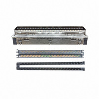
CONN MDR PLUG 80POS IDC GOLD
Manufacturer
3M
Series
101, Mini D Ribbon (MDR)r
Datasheet
1.N3314-620T02RB.pdf
(6 pages)
Specifications of 10180-6000EC
Connector Style
Center Strip Contacts
Connector Type
Plug
Number Of Positions
80
Number Of Rows
2
Mounting Type
Free Hanging (In-Line)
Termination
IDC
Features
Shielded
Contact Finish
Gold
Contact Finish Thickness
30µin (0.76µm)
Product
Micro Hoods & Connectors
Number Of Positions / Contacts
80
Current Rating
1 A
Contact Plating
Gold
Shell Plating
Nickel
Gender
Male
Mounting Style
IDC
Termination Style
Crimp
Lead Free Status / RoHS Status
Lead free / RoHS Compliant
Other names
101806000EC
4901690086458
90169008645
JE150174918
MPB80A
4901690086458
90169008645
JE150174918
MPB80A


3M
.100” × .100” Latch/Ejector, Straight, Compliant Pin
3
Electronic Solutions Division
Interconnect Solutions
http://www.3M.com/interconnects/
Ordering Information
Note:
3. Listed below are the PCB hole sizes and tolerances recommended for use with 3M’s compliant
4. Use of snap-in latch/ejectors in either short (N3XXX-650T02XX) or long (N3XXX-660T02XX)
Assembly Equipment: Use 3442-00XX platen (see chart above) and
appropriate commercial arbor press to press header into pc board.
If ordering Snap-In style latches separately, please use the chart below
pin header. The insertion force is designed not to exceed 40 pounds per pin and the withdrawal
force is not less than 10 pounds per pin.
styles, installed or shipped separately. (-5 & -6 snap-in latches are dimensionally and functionally
equivalent to -2 & -3 roll pin latches)
High Temp (PPA)
High Temp (PPA)
.100 ± .003
[2.54]
Prefix:
Blank = Std.Temp Gray (PBT): (TC Plating Req’d)
N = High Temp Black (PCT) (RB Plating Req’d)
™
[1.52]
.060
Pin Qty
Recommended Mounting Hole Pattern
10
14
16
20
24
26
30
34
40
50
60
64
Four-Wall Header
.300 Min
[7.62]
Side to Side
Stackability
Number
3M Part
3793
3314
3408
3428
3627
3429
3440
3431
3432
3433
3372
3764
Position 1
Short Latch
N3505-30B
3.96 (100.7)
3505-30
1.26 (32.1)
1.46 (37.2)
1.76 (44.8)
1.96 (49.9)
2.06 (52.4)
2.26 (57.5)
2.46 (62.6)
2.76 (70.2)
3.76 (95.6)
(See Note 2)
1.56 (39.7)
3.26 (82.9)
[2.69]
.106
See Note 3
.100 ± .003
[2.54]
A
[8.94]
B
.352
or
3M Part Number
[2.95]
.116
1.105 (28.07)
1.305 (33.15)
1.405 (35.69)
1.605 (40.77)
1.805 (45.85)
1.905 (48.39)
2.105 (53.47)
2.305 (58.55)
2.605 (66.17)
3.105 (78.87)
3.605 (91.57)
3.805 (96.65)
N3505-31B
Long Latch
3505-31
B
X XXXX - 6X0T02XX
Dimensions
Latch/Ejector System:
0 = No latch/ejectors
2 = Short latch/ejectors
3 = Long latch/ejectors
5 = Short, Snap-In Latch/Ejectors
6 = Long, Snap-In Latch/Ejectors
Black
Color
Gray
0.865 (21.97)
1.065 (27.05)
1.165 (29.59)
1.365 (34.67)
1.565 (39.75)
1.665 (42.29)
1.865 (47.37)
2.065 (52.45)
2.365 (60.07)
2.865 (72.77)
3.365 (85.47)
3.565 (90.55)
Section T-T
Section
Tail
R
R
C
4X .002 ± .001
Break Edges
[0.05]
Compliant Section
Plating suffix:
TC = 30 μ” Gold w/Tin-Lead Tails (App. E2 & C2 Apply)
RB = 30 μ” Gold w/Matte Tin Tails (App. E1 & C1 Apply)
0.71 (18.0)
0.91 (23.1)
1.01 (25.6)
1.21 (30.7)
1.41 (35.8)
1.51 (38.3)
1.71 (43.4)
1.91 (48.5)
2.21 (56.1)
2.71 (68.8)
3.21 (81.5)
3.41 (86.6)
For technical, sales or ordering information call
S
S
D
Hole Size for:
Preferred Drilled - ø.0453 ± .0005
Acceptable Drilled - ø.0453 +.0005
-.0010
After Etchback - ø.0460 Max
After Plating - .ø040 ± .003
Board thickness - .093 to .150
Plating:
.001 Minimum Copper plating thickness
.0003 Min Tin plating
Pin Cross Sections
Section R-R
Section S-S
3M is a trademark of 3M Company.
Polarizing
Provided
Notches
ABC
ABC
ABC
ABC
ABC
ABC
ABC
ABC
ABC
ABC
BC
BC
4X R .009 Max
R .020 Sym
[0.23]
[0.51]
Insertion platen
3442-0048
3442-0049
3442-0050
3442-0051
3442-0052
3442-0053
3442-0054
3442-0055
3442-0056
3442-0057
3442-0058
3442-0059
3442-00XX
T
T
Mating
3000 Series
Area
800-225-5373
Sheet 3 of 3
TS-0478-B
Related parts for 10180-6000EC
Image
Part Number
Description
Manufacturer
Datasheet
Request
R


Part Number:
Description:
ANTENNA, GPS, 3M CABLE, SMA
Manufacturer:
WI-SYS
Datasheet:
Part Number:
Description:
ANTENNA, GPS, 3M CABLE, SMA
Manufacturer:
WI-SYS
Datasheet:
Part Number:
Description:
ANTENNA, GPS, 3M CABLE, SMA
Manufacturer:
WI-SYS
Datasheet:

Part Number:
Description:
3M MPro Car Charger
Manufacturer:
3M
Datasheet:

Part Number:
Description:
3M-MINI-CLAMP/PLUG/WMIC/2MM/3POS/TYPE A/ORANGE/3M LOGO
Manufacturer:
3M
Datasheet:
Part Number:
Description:
3M-MINI-CLAMP/PLUG/WMIC/2MM/4POS/TYPE A/YELLOW/3M LOGO
Manufacturer:
3M
Datasheet:
Part Number:
Description:
3M-MINI-CLAMP/PLUG/WMIC/2MM/4POS/TYPE A/ORANGE/3M LOGO
Manufacturer:
3M
Datasheet:
Part Number:
Description:
3M-MINI-CLAMP/SKT PANELMOUNT/WMIC/2MM/3POS/TYPE A/RED/3M LOGO
Manufacturer:
3M
Datasheet:
Part Number:
Description:
3M-MINI-CLAMP/SKT PANELMOUNT/WMIC/2MM/3POS/TYPE A/YELLOW/3M LO
Manufacturer:
3M
Datasheet:
Part Number:
Description:
3M-MINI-CLAMP/SKT/WMIC/2MM/3POS/TYPE A/ORANGE/3M LOGO
Manufacturer:
3M
Datasheet:
Part Number:
Description:
3M-MINI-CLAMP/SKT PANELMOUNT/WMIC/2MM/3POS/TYPE A/ORANGE/3M LO
Manufacturer:
3M
Datasheet:
Part Number:
Description:
3M-MINI-CLAMP/SKT PANELMOUNT/WMIC/2MM/4POS/TYPE A/RED/3M LOGO
Manufacturer:
3M
Datasheet:
Part Number:
Description:
3M-MINI-CLAMP/SKT/WMIC/2MM/4POS/TYPE A/YELLOW/3M LOGO
Manufacturer:
3M
Datasheet:
Part Number:
Description:
3M-MINI-CLAMP/SKT PANELMOUNT/WMIC/2MM/4POS/TYPE A/YELLOW/3M LO
Manufacturer:
3M
Datasheet: