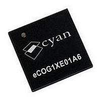
ECOG1XE01A6 CYAN, ECOG1XE01A6 Datasheet - Page 80

ECOG1XE01A6
Manufacturer Part Number
ECOG1XE01A6
Description
IC, 16BIT MCU, ECOG1X, 70MHZ, QFN-68
Manufacturer
CYAN
Datasheet
1.ECOG1X14Z5.pdf
(95 pages)
Specifications of ECOG1XE01A6
Controller Family/series
ECOG1X
No. Of I/o's
20
Ram Memory Size
8KB
Cpu Speed
70MHz
No. Of Timers
8
Digital Ic Case Style
QFN
Core Size
16 Bit
Program Memory Size
64KB
Embedded Interface Type
I2C, JTAG, SPI, UART
Rohs Compliant
Yes
Lead Free Status / RoHS Status
Lead free / RoHS Compliant
Version 1.15
Peripheral Clock Frequency Limits
1
2
3
4
80
The clock sources, PLLs and SSM provide clock signals to the on-chip peripheral modules over a wide
frequency range. There are maximum (and in some cases minimum) frequency limits on the clock
signals provided by the SSM to the peripheral modules.
The following table lists any limits or constraints on input clock frequencies for the CPU and the on-chip
peripherals, after the SSM clock dividers and prescalers. Note that each frequency listed here is the
absolute maximum internal clock frequency for the peripheral. This means only that the internal
peripheral hardware can be clocked at this maximum frequency, it does not mean that the complete
peripheral function including external signals operates successfully at this frequency. Input and output
delay times and pin loadings must be taken into account when determining the maximum operating
frequency for any peripheral including external signals.
If the high PLL is used as the memory clock source and the EMI peripheral is used, then the high PLL output
frequency must be limited to a maximum of 385MHz. If the EMI peripheral is not used, the maximum high PLL
output frequency of 400MHz can be used to generate the internal memory and CPU clocks.
The maximum useful DAC clock frequency is 250kHz since the DAC analogue output has a settling time of 4µs.
The DAC interface logic can be clocked at much higher frequencies.
The EMAC peripheral is fully static and has a minimum clock frequency of zero. To support data communication at
either 10Mb/s or 100Mb/s, higher minimum clock frequencies are required as shown.
The USB core is also fully static and has a minimum clock frequency of zero. However, in normal operation it
requires a 48.0 MHz clock in order to meet the USB standard timing specifications.
Module
CPU
EMI
Timer
Counter/timers
PWM timers
Capture timer
Watchdog timer
Long interval timer
DUART
DUSART
Flash memory timer
ADC
DAC
ESPI
I
LCD
MCPWM
DSCI
EMAC
USB
2
S
1
eCOG and CyanIDE are registered trademarks of Cyan Holdings plc
4
2
3
eCOG1X Microcontroller Product Family
Table 50: Internal clock frequency limits
www.cyantechnology.com
TMR
CNT1
CNT2
PWM1
PWM2
CAP
WDOG
LTMR
UART1A
UART1B
UART2A
UART2B
12 bits
10 bits
8 bits
6 bits
10Mb/s
100Mb/s
Clock frequency (MHz)
Min.
3.0
30
0
0
0
0
0
0
0
0
0
0
0
0
0
0
0
0
0
0
0
0
0
0
0
0
0
0
48 ± 0.05%
Max.
0.25
150
175
192
189
206
194
203
196
140
195
215
202
202
175
209
364
158
172
3.2
4.9
6.0
8.0
71
86
78
87
87
4 August 2009


