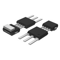
KMI15/4,115 NXP Semiconductors, KMI15/4,115 Datasheet - Page 10

KMI15/4,115
Manufacturer Part Number
KMI15/4,115
Description
SPEED SENSOR ROTATIONAL SOT453C
Manufacturer
NXP Semiconductors
Type
Special Purposer
Datasheet
1.KMI154115.pdf
(16 pages)
Specifications of KMI15/4,115
Sensing Range
0mm ~ 2.3mm
Voltage - Supply
5.5 V ~ 16 V
Current - Output (max)
8.4mA
Output Type
Digital, Open Collector
Features
Gear Tooth Type
Operating Temperature
-40°C ~ 85°C
Package / Case
SOT-453C
Maximum Operating Temperature
+ 85 C
Mounting Style
Through Hole
Lead Free Status / RoHS Status
Lead free / RoHS Compliant
Current - Supply
-
Lead Free Status / Rohs Status
Compliant
Other names
934050800115
KMI15/4 T/R
KMI15/4 T/R
KMI15/4 T/R
KMI15/4 T/R
Available stocks
Company
Part Number
Manufacturer
Quantity
Price
Part Number:
KMI15/4,115
Manufacturer:
NXP/恩智浦
Quantity:
20 000
Philips Semiconductors
EMC
Figure 18 shows a recommended application circuit for
automotive applications (wheel sensing f
It provides a protection interface to meet Electromagnetic
Compatibility (EMC) standards and safeguard against
voltage spikes Table 1 lists the tests which are applicable
to this circuit and the achieved class of functional status.
Protection against ‘load dump’ (test pulse 5 according to
“DIN 40839” ) means a very high demand on the protection
circuit and requires a suitable suppressor diode with
sufficient energy absorption capability.
Table 1 EMC test results
2000 Sep 05
Test pulse 1
Test pulse 2
Test pulse 3a
Test pulse 3b
Test pulse 4
Test pulse 5
EMC REF. DIN 40839
Rotational speed sensor
V
V
V
V
V
V
LD
LD
LD
LD
LD
LD
SYMBOL
handbook, halfpage
GND
V
Fig.18 Test/application circuit for the KMI15/4.
BZTO3G36
1N4001/3
t
D1
< 5 kHz).
100
150
7
MIN. (V)
D2
100
C1
nF
10
The board net often contains a central load dump
protection that makes such a device in the protection
circuit of the sensor module unnecessary.
Tests for electrostatic discharge (ESD) were conducted in
line with “IEC 801-2” to demonstrate the KMI15/4’s
handling capabilities. The “IEC 801-2” test conditions
were: C = 150 pF, R = 150 , V = 2 kV.
Electromagnetic disturbances with fields up to 150 V/m
and f = 1 GHz (ref. “DIN 40839” ) have no influence on
performance.
115
R L
100
100
120
MAX. (V)
100
C L
nF
V CC
V
SENSOR
MGD805
t
t
t
t
t
t
d
d
d
d
d
d
= 2 ms
= 0.2 ms
= 0.1 s
= 0.1 s
= 130 ms
= 400 ms
REMARKS
Product specification
C
A
A
A
B
B
KMI15/4
CLASS


