PAXR0000 Red Lion Controls, PAXR0000 Datasheet - Page 7
PAXR0000
Manufacturer Part Number
PAXR0000
Description
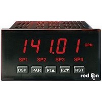
Rate Counter
Manufacturer
Red Lion Controls
Type
Rate Indicatorr
Specifications of PAXR0000
No. Of Digits / Alpha
6
Signal Input Type
Pulse
Character Size
0.56"
Ip/nema Rating
IP65 / NEMA 4X
Panel Cutout Height
1.77"
Display Font Color
Red
Panel Cutout Width
3.62"
Counter Supply Voltage
85-250VAC
Accuracy
±0.01% %
Connection Type
Cage-Clamp
Cut Out, Panel
1/8 DIN
Digit Height
0.56
Dimensions
4.2"L×3.8"W×1.95"H
Display Digit Height
0.56 "
Display Type
LED
Function
Rate Indicator
Indicator Type
Rate Meter
Number Of Digits
6
Primary Type
Electronic
Range, Measurement
0 to 99999
Special Features
Programmable Function Keys
Temperature, Operating, Range
0 to 50 °C
Termination
Cage Clamp
Voltage, Supply
85 to 250 VAC
Lead Free Status / RoHS Status
Lead free / RoHS Compliant


case by firmly squeezing and pulling back on the side rear finger tabs. This
should lower the latch below the case slot (which is located just in front of the
finger tabs). It is recommended to release the latch on one side, then start the
other side latch.
2.1 SETTING THE JUMPER
this jumper must be set before applying power. The Main Circuit Board figure
shows the location of the jumper and DIP switch.
are used with user functions or for input signal direction. All user inputs are set
by this jumper.
1.0 I
2.0 S
Installation
unit is intended to be mounted into an enclosed panel. Prepare the panel cutout
to the dimensions shown. Remove the panel latch from the unit. Slide the panel
gasket over the rear of the unit to the back of the bezel. The unit should be
installed fully assembled. Insert the unit into the panel cutout.
To access the jumper and switches, remove the meter base from the meter
The meter has one jumper for user input logic. When using the user inputs
The user input jumper determines signal logic for the user inputs, when they
The PAX meets NEMA 4X/IP65 requirements when properly installed. The
BEZEL
PANEL
GASKET
LATCHING
NSTALLING THE
SLOTS
ETTING THE
INPUT SET-UP
DIP SWITCHES
Main
Circuit
Board
PANEL
SRC
J
PANEL
MOUNTING
SCREWS
UMPER AND
SNK
USER
INPUT
JUMPER
M
PANEL
LATCH
LATCHING
TABS
ETER
7
so that the tabs of the panel latch engage in the slots on the case. The panel
latch should be engaged in the farthest forward slot possible. To achieve a
proper seal, tighten the latch screws evenly until the unit is snug in the panel
(Torque to approximately 7 in-lbs [79N-cm]). Do not over-tighten the screws.
Installation Environment
temperature and provides good air circulation. Placing the unit near devices
that generate excessive heat should be avoided.
Do NOT use solvents. Continuous exposure to direct sunlight may accelerate
the aging process of the bezel.
keypad of the unit.
2.2 SETTING THE INPUT DIP SWITCHES
must be set before applying power. NOTE: The PAXR only uses switches 1-3.
SWITCHES 3 and 6
HI Frequency: Removes damping capacitor and allows max. frequency.
LO Frequency: Adds a damping capacitor for switch contact bounce. Also
SWITCHES 2 and 5
SRC.: Adds internal 3.9 K pull-down resistor, 7.3 mA max. @ 28 VDC,
V
SNK.: Adds internal 7.8 K pull-up resistor to +12 VDC, I
SWITCHES 1 and 4
LOGIC: Input trigger levels V
MAG: 200 mV peak input (must also have SRC on). Not recommended with
MAX
While holding the unit in place, push the panel latch over the rear of the unit
The unit should be installed in a location that does not exceed the operating
The bezel should only be cleaned with a soft cloth and neutral soap product.
Do not use tools of any kind (screwdrivers, pens, pencils, etc.) to operate the
The meter has six DIP switches for Input A and Input B terminal set-up that
limits input frequency to 50 Hz and input pulse widths to 10 msec.
counting applications.
= 30 VDC.
Warning: Exposed line voltage exists on the circuit boards. Remove
DIP S
all power to the meter and load circuits before accessing inside of
the meter.
Input B LO Freq.
Input B SRC.
Input B MAG.
Input A LO Freq.
Input A SRC.
Input A MAG.
IL
ON
PANEL CUT-OUT
WITCHES
= 1.5 V max.; V
Factory Setting
1
6
4
3
2
5
HI Freq.
SNK.
Logic
HI Freq.
SNK.
Logic
IH
= 3.75 V min.
MAX
= 1.9 mA.
Related parts for PAXR0000
Image
Part Number
Description
Manufacturer
Datasheet
Request
R

Part Number:
Description:
Counter
Manufacturer:
Red Lion Controls
Datasheet:
Part Number:
Description:
Miniature Length Sensor
Manufacturer:
Red Lion Controls
Datasheet:
Part Number:
Description:
Model Lsc - Single Channel Output Length Sensor
Manufacturer:
Red Lion Controls
Datasheet: