TSOP2140SA1 Vishay, TSOP2140SA1 Datasheet - Page 2
TSOP2140SA1
Manufacturer Part Number
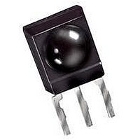
TSOP2140SA1
Description
IR RECEIVER, 35M, 950NM, SIP
Manufacturer
Vishay
Datasheet
1.TSOP2140SA1.pdf
(7 pages)
Specifications of TSOP2140SA1
Transmission Range
35m
Directivity
45°
Supply Voltage Range
4.5V To 5.5V
Opto Case Style
Through Hole
Operating Temperature Range
-25°C To +85°C
Carrier Frequency
40kHz
Supply Current
1.4mA
Lead Free Status / RoHS Status
Lead free / RoHS Compliant


TSOP21..SA1
Vishay Semiconductors
Absolute Maximum Ratings
T
Electrical and Optical Characteristics
T
Typical Characteristics
Document Number 82160
Rev. 2, 15-Oct-2002
V
V
V
Supply Voltage
Supply Current
Output Voltage
Output Current
Junction Temperature
Storage Temperature Range
Operating Temperature Range
Power Consumption
Soldering Temperature
Supply Current (Pin 2)
Supply Voltage (Pin 2)
Transmission Distance
Output Voltage Low (Pin 1)
Irradiance (30 - 40 kHz)
Irradiance (56 kHz)
Irradiance
Directivity
amb
amb
O
OH
OL
E
e
= 25 °C, unless otherwise specified
= 25 °C, unless otherwise specified
Optical Test Signal
(IR diode TSAL6200, I
Output Signal
t
d
1 )
*) t
t
pi
pi
1 )
2 )
Parameter
*)
w 6/fo is recommended for optimal function
3/f
t
pi
0
– 4/f
< t
Parameter
Figure 1. Output Function
d
0
< 9/f
t
< t
po
2 )
F
po
T
0
=0.4 A, N=6 pulses, f=f
< t
pi
+ 6/f
0
V
V
E
diode TSAL6200, I
I
f
Pulse width tolerance: t
< t
Pulse width tolerance: t
< t
Test signal see fig. 1
Angle of half transmission distance
o
OL
(T
S
S
v
, test signal see fig.1
pi
pi
= 0, test signal see fig.3, IR
= 5 V, E
= 5 V, E
= 0.5 mA, E
amb
+ 6/f
+ 6/f
0
, T=10 ms)
o
o
= 25°C unless otherwise specified)
, test signal see fig.3
, test signal see fig.3
Test condition
v
v
t
(Pin 2)
(Pin 2)
(Pin 1)
(Pin 1)
(T
t ≤ 10 s, 1 mm from case
14337
= 0
= 40 klx, sunlight
t
amb
e
= 0.7 mW/m
≤ 85 °C)
F
= 250 mA
pi
pi
- 5/f
- 5/f
o
o
Test condition
2
< t
< t
, f =
po
po
16907
Symbol
Figure 2. Pulse Length and Sensitivity in Dark Ambient
E
E
E
0.35
0.30
0.25
0.20
0.15
0.10
0.05
0.00
V
ϕ
e max
I
I
e min
e min
V
SD
SH
d
OL
1/2
S
0.1
1.0
E
optical test signal, fig.1
Min
Input Burst Duration
e
0.8
4.5
30
Output Pulse
– Irradiance ( mW/m
10.0
l = 950 nm,
100.0 1000.010000.0
Symbol
T
T
P
T
V
V
amb
I
I
T
± 45
Typ.
stg
O
S
tot
sd
1.1
1.4
0.2
0.3
O
S
35
j
2
)
- 25 to + 85
- 25 to + 85
- 0.3 to +
- 0.3 to +
Value
Max
250
100
260
1.5
5.5
0.4
0.5
6.0
6.0
50
5
5
www.vishay.com
VISHAY
mW/m
mW/m
W/m
Unit
deg
mA
mA
mV
m
Unit
mW
V
mA
mA
°C
°C
°C
°C
V
V
2
2
2
2
Related parts for TSOP2140SA1
Image
Part Number
Description
Manufacturer
Datasheet
Request
R

Part Number:
Description:
TSOP 48/I�/8GX8 NAND FLASH PLASTIC IND TEMP PBF TSOP 3.3V ASYNCH/PAGE READ
Manufacturer:
Micron Semiconductor Products
Part Number:
Description:
TSOP 66/I�/64MX16 DDR SDRAM PLASTIC PBF TSOP 2.5V
Manufacturer:
Micron Semiconductor Products
Datasheet:
Part Number:
Description:
TSOP 54/I�/256MB 16MX16 SDRAM PLASTIC IND TEMP TSOP 3.3V
Manufacturer:
Micron Semiconductor Products
Datasheet:

Part Number:
Description:
TSOP/16MX16 SDRAM PLASTIC PBF TSOP 3.3V 200MHZ
Manufacturer:
Hynix Semiconductor
Part Number:
Description:
TSOP/16MX16 SDRAM PLASTIC PBF TSOP 3.3V 200MHZ
Manufacturer:
Hynix Semiconductor
Datasheet:
Part Number:
Description:
TSOP 66/C�/64MX8 DDR SDRAM PLASTIC PBF TSOP 2.6V tape and reel
Manufacturer:
Hynix Semiconductor

Part Number:
Description:
TSOP-1 48 12X20 CUSTD FLASH
Manufacturer:
NUMONYX
Datasheet:

Part Number:
Description:
TSOP, IND TEMP, GREEN(DATA FLASH)
Manufacturer:
ATMEL Corporation

Part Number:
Description:
Manufacturer:
Infineon Technologies
Datasheet:
Part Number:
Description:
Manufacturer:
Infineon Technologies
Datasheet:
Part Number:
Description:
Manufacturer:
Infineon Technologies
Datasheet:
Part Number:
Description:
Manufacturer:
Infineon Technologies
Datasheet:
Part Number:
Description:
Manufacturer:
Infineon Technologies
Datasheet: