TSOP6137TR Vishay, TSOP6137TR Datasheet - Page 5
TSOP6137TR
Manufacturer Part Number
TSOP6137TR
Description
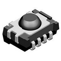
IR RECEIVER, 40M, 950NM, SMD
Manufacturer
Vishay
Datasheet
1.TSOP6138TR.pdf
(12 pages)
Specifications of TSOP6137TR
Transmission Range
40m
Directivity
50°
Supply Voltage Range
2.7V To 5.5V
Opto Case Style
SMD
Operating Temperature Range
-25°C To +85°C
Carrier Frequency
36.7kHz
Supply Current
950µA
Lead Free Status / RoHS Status
Lead free / RoHS Compliant


SUITABLE DATA FORMAT
The TSOP61.., TSOP63.. series are designed to suppress
spurious output pulses due to noise or disturbance signals.
Data and disturbance signals can be distinguished by the
devices according to carrier frequency, burst length and
envelope duty cycle. The data signal should be close to the
band-pass center frequency (e.g. 38 kHz) and fulfill the
conditions in the table below.
When a data signal is applied to the TSOP61.., TSOP63.. in
the presence of a disturbance signal, the sensitivity of the
receiver is reduced to insure that no spurious pulses are
present at the output. Some examples of disturbance
signals which are suppressed are:
• DC light (e.g. from tungsten bulb or sunlight)
• Continuous signals at any frequency
• Modulated IR signals from common fluorescent lamps
Note
• For data formats with long bursts (10 carrier cycles or longer) we recommend the TSOP62.., TSOP 64.. because of the better noise
Document Number: 82176
Rev. 2.4, 04-Feb-11
Minimum burst length
After each burst of length
a minimum gap time is required of
For bursts greater than
a minimum gap time in the data stream is needed of
Maximum number of continuous short bursts/second
Recommended for NEC code
Recommended for RC5/RC6 code
Recommended for Sony code
Recommended for RECS-80 code
Recommended for RCMM code
Recommended for r-step code
Recommended for XMP code
Suppression of interference from fluorescent lamps
(example of noise pattern is shown in fig. 14 or fig. 15)
suppression.
IR Receiver Modules for Remote
Control Systems
supressed (e.g. waveform of figure 14)
Common disturbance signals are
> 1.1 x burst length
6 cycles/burst
6 to 70 cycles
10 cycles
TSOP61..
70 cycles
2000
yes
yes
yes
yes
yes
yes
yes
16921
16920
Fig. 14 - IR Signal from Fluorescent Lamp
Fig. 15 - IR Signal from Fluorescent Lamp
0
0
with High Modulation
with Low Modulation
5
TSOP61.., TSOP63..
5
Vishay Semiconductors
suppressed (e.g. waveform of figure 15)
Even critical disturbance signals are
Time (ms)
Time (ms)
10
10
> 6 x burst length
6 cycles/burst
6 to 35 cycles
10 cycles
TSOP63..
35 cycles
2000
15
15
yes
yes
yes
yes
yes
yes
yes
www.vishay.com
20
20
5
Related parts for TSOP6137TR
Image
Part Number
Description
Manufacturer
Datasheet
Request
R

Part Number:
Description:
Ir Receiver Modules For Remote Control Systems
Manufacturer:
Vishay
Datasheet:

Part Number:
Description:
TSOP 48/I�/8GX8 NAND FLASH PLASTIC IND TEMP PBF TSOP 3.3V ASYNCH/PAGE READ
Manufacturer:
Micron Semiconductor Products
Part Number:
Description:
TSOP 66/I�/64MX16 DDR SDRAM PLASTIC PBF TSOP 2.5V
Manufacturer:
Micron Semiconductor Products
Datasheet:
Part Number:
Description:
TSOP 54/I�/256MB 16MX16 SDRAM PLASTIC IND TEMP TSOP 3.3V
Manufacturer:
Micron Semiconductor Products
Datasheet:

Part Number:
Description:
TSOP/16MX16 SDRAM PLASTIC PBF TSOP 3.3V 200MHZ
Manufacturer:
Hynix Semiconductor
Part Number:
Description:
TSOP/16MX16 SDRAM PLASTIC PBF TSOP 3.3V 200MHZ
Manufacturer:
Hynix Semiconductor
Datasheet:
Part Number:
Description:
TSOP 66/C�/64MX8 DDR SDRAM PLASTIC PBF TSOP 2.6V tape and reel
Manufacturer:
Hynix Semiconductor

Part Number:
Description:
TSOP-1 48 12X20 CUSTD FLASH
Manufacturer:
NUMONYX
Datasheet:

Part Number:
Description:
TSOP, IND TEMP, GREEN(DATA FLASH)
Manufacturer:
ATMEL Corporation

Part Number:
Description:
Manufacturer:
Infineon Technologies
Datasheet:
Part Number:
Description:
Manufacturer:
Infineon Technologies
Datasheet:
Part Number:
Description:
Manufacturer:
Infineon Technologies
Datasheet:
Part Number:
Description:
Manufacturer:
Infineon Technologies
Datasheet: