M20-ANT RF Solutions, M20-ANT Datasheet - Page 15
M20-ANT
Manufacturer Part Number
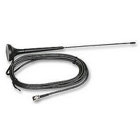
M20-ANT
Description
ANTENNA, MAESTRO 20
Manufacturer
RF Solutions
Datasheet
1.M20-ANT.pdf
(26 pages)
Specifications of M20-ANT
Svhc
No SVHC (15-Dec-2010)


DS020-7 Oct ‘06
CHAPTER 5
APPENDIX
5.1 Factory settings
The modem has the following factory settings. Please refer to the AT command document for the meaning of each
setting.
AT+IPR
AT+IFC
AT+ICF
ATE
AT&C
AT&D
ATQ
ATV
AT&S
ATS0
AT+CLIP
AT+CRLP
AT+CSCS
AT+CMGF
AT+CSMP
AT+CNMI
5.2 Input / Output port
This port can be configured as either an input one or an output one.
To configure it as an input port, first issue AT+WIOW=2, 0 to disable the output port. Use AT+WIOR=3(Fargo
Maestro 100) or AT+WIOR=1(Fargo Maestro 20) to read the status of this input port. Response +WIOR: 0
represent Logic HIGH (>3V); Response +WIOR: 1 represent Logic LOW (<0.5V) To use it as an output port, issue
AT+WIOW=2,1 will turn it on and it will drain current to ground. The current is recommended not to exceed 10 mA.
Issue AT+WIOW=2,0 will turn it off.
5.3 RS232 AUTO-ONLINE mode (power saving)
When being in the AUTO-ONLINE, the RS232 transceiver will shutdown most of its hardware to save power if it
does not detect a valid input for more than 100uS. The RS232 transceiver will wake up when valid input is detected
again.
By default, the RS232 transceiver is put in AUTO-ONLINE. This mode can be turned off by issuing AT+WIOW=4,1.
Related AT commands
GSM100 U
2,2
9600
3,4
1
1
1
0
1
1
0
0
“PCCP437”
1
1,67,0,0
0,0,0,0
©2006 REG No 277 4001, ENGLAND.
Factory Settings
SERS
DTE-DCE data rate
DTE-DCE flow control
DTE-DCE character framing
ECHO
DCD signal
DTR signal
Result code suppression
Response format
DSR signal
Auto answer
Calling line ID presentation
Calling line ID restriction
Message format
Text mode parameters
New message indication
M
ANUAL
Description
Page 15
Related parts for M20-ANT
Image
Part Number
Description
Manufacturer
Datasheet
Request
R

Part Number:
Description:
MOUNT, DIN RAIL
Manufacturer:
RF Solutions
Datasheet:

Part Number:
Description:
RF Switch SPDT 0MHz to 2GHz 27dB 8-Pin SOIC T/R
Manufacturer:
M/A-Com Technology Solutions
Datasheet:
Part Number:
Description:
RF Switch SPST 500MHz to 2GHz 40dB 8-Pin SOIC T/R
Manufacturer:
M/A-Com Technology Solutions
Datasheet:

Part Number:
Description:
RF Switch SPDT 100MHz to 4GHz 14dB 6-Pin SOT-6
Manufacturer:
Skyworks Solutions Inc
Datasheet:

Part Number:
Description:
IC ENCODER TRANSMITTER RF 8DIP
Manufacturer:
RF Solutions
Datasheet:

Part Number:
Description:
IC DECODER RECEIVER RF 18DIP
Manufacturer:
RF Solutions
Datasheet:

Part Number:
Description:
IC ENCODER 3 DGTL I/O SOT23-6
Manufacturer:
RF Solutions
Datasheet:

Part Number:
Description:
IC ENCODER 3 DGTL I/O 8-PDIP
Manufacturer:
RF Solutions
Datasheet:

Part Number:
Description:
IC DECODER 3 DGTL I/O 8-PDIP
Manufacturer:
RF Solutions
Datasheet:

Part Number:
Description:
IC DECODER 3 DGTL I/O 8-SOIC
Manufacturer:
RF Solutions
Datasheet:

Part Number:
Description:
118 SERIES AM REMOTE CONTROL SYSTEMS.
Manufacturer:
RF Solutions Ltd.