FLEX104 EVIDENCE, FLEX104 Datasheet - Page 14
FLEX104
Manufacturer Part Number
FLEX104
Description
Development Tools & Eval/Demo Boards
Manufacturer
EVIDENCE
Datasheet
1.FLEX103.pdf
(41 pages)
Specifications of FLEX104
Silicon Manufacturer
Microchip
Application Sub Type
FLEX Multibus RS485 Module
Kit Application Type
Communication & Networking
Kit Contents
Board
Supply Voltage Range
7V To 12V, 9V To 36V
Lead Free Status / RoHS Status
Lead free / RoHS Compliant


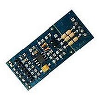
3.1.2 Base board: Light version
The Light FLEX Base Board, depicted in Figure 3.7, has been designed to be as compact
as possible. The Light Versions uses a simplified power supply circuitry, and thus requires
a more careful power supply than the Full Version. Moreover, there is no integrated
USB programming capability. Examples of target applications for the Light FLEX Base
Board are: distributed, battery-powered applications, like sensor networks; small robotic
applications, i.e., for mobile robot control and sensor acquisition.
Figure
power supply connector. Connect the source voltage to the first two pins, named in
figure as V+ and V-.
The power supply of the Light FLEX Base Board varies in the range of 9 - 12V DC.
• JP12: toggle the programming clock line coming from the ICSP programming
• JP13: connects the pull-up resistor to the RX serial line; if unused, the pin is used
• JP15 and JP16: allows to use an external clock oscillator for the dsPIC (R) DSC;
• JP17: allow to toggle the USB shield between GND or PE.
connector between dsPIC (R) DSC and PIC18 micro-controllers;
as a regular GPIO pin;
if disabled, the two pins are used as normal GPIO pins;
3.8
shows a rear view of the Flex Light board. On the top right, there are the
Figure 3.7: FLEX light version.
14
Related parts for FLEX104
Image
Part Number
Description
Manufacturer
Datasheet
Request
R

Part Number:
Description:
FLEX Light Base Board
Manufacturer:
EVIDENCE
Datasheet:

Part Number:
Description:
FLEX MultiBus Daughter Board
Manufacturer:
EVIDENCE
Datasheet:

Part Number:
Description:
FLEX Demo Daughter Board
Manufacturer:
EVIDENCE
Datasheet:

Part Number:
Description:
FLEX Full Base Board
Manufacturer:
EVIDENCE
Datasheet:

Part Number:
Description:
FLEX Blank Thru-Hole Daughter Board
Manufacturer:
EVIDENCE
Datasheet:

Part Number:
Description:
FLEX Multibus Ethernet Module
Manufacturer:
EVIDENCE
Datasheet:

Part Number:
Description:
FLEX Multibus RS232 Module
Manufacturer:
EVIDENCE
Datasheet:

Part Number:
Description:
FLEX Multibus RS422 Module
Manufacturer:
EVIDENCE
Datasheet:

Part Number:
Description:
FLEX Multibus CAN Module
Manufacturer:
EVIDENCE
Datasheet:

Part Number:
Description:
FLEX Multibus SPI Module
Manufacturer:
EVIDENCE
Datasheet:


Part Number:
Description:
Microcontroller & Microprocessor Development Tools Demo2 Pack
Manufacturer:
EVIDENCE
Datasheet:

Part Number:
Description:
Microcontroller & Microprocessor Development Tools Mini Kit
Manufacturer:
EVIDENCE
Datasheet:

Part Number:
Description:
Microcontroller & Microprocessor Development Tools Multibus Pack
Manufacturer:
EVIDENCE
Datasheet: