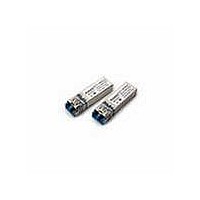
HFCT-5953TL Avago Technologies US Inc., HFCT-5953TL Datasheet - Page 10

HFCT-5953TL
Manufacturer Part Number
HFCT-5953TL
Description
Fiber Optic Transmitters, Receivers, Transceivers OC12 IR 2x5 SFF LC
Manufacturer
Avago Technologies US Inc.
Datasheet
1.HFCT-5953TL.pdf
(17 pages)
Specifications of HFCT-5953TL
Function
High performance, modules for serial optical data communication applications, designed for single mode fiber.
Product
Transceiver
Data Rate
622 Mbps
Wavelength
1300 nm
Maximum Rise Time
1 ns, 0.5 ns
Maximum Fall Time
1 ns, 0.5 ns
Maximum Output Current
50 mA
Operating Supply Voltage
3.14 V to 3.47 V
Maximum Operating Temperature
+ 70 C
Minimum Operating Temperature
0 C
Package / Case
DIP-10 with Connector
Optical Fiber Type
TX/RX
Data Transfer Rate
622Mbps
Optical Rise Time
1/0.5ns
Optical Fall Time
1/0.5ns
Operating Temperature Classification
Commercial
Peak Wavelength
1356/1570nm
Package Type
DIP With Connector
Operating Supply Voltage (min)
3.14V
Operating Supply Voltage (typ)
3.3V
Operating Supply Voltage (max)
3.47V
Output Current
50mA
Operating Temp Range
0C to 70C
Mounting
Snap Fit To Panel
Pin Count
10
For Use With
Singlemode Glass
Lead Free Status / RoHS Status
Lead free / RoHS Compliant
10
Figure 9 - Recommended Board Layout Hole Pattern
Power Supply Filtering and Ground Planes
It is important to exercise care in circuit board layout
to achieve optimum performance from these trans-
ceivers. Figures 7 and 8 show the power supply circuit
which complies with the small form factor multisource
agreement. It is further recommended that a continu-
ous ground plane be provided in the circuit board di-
rectly under the transceiver to provide a low inductance
ground for signal return current. This recommendation
is in keeping with good high frequency board layout
practices.
Package footprint and front panel considerations
The Avago Technologies transceiver complies with the
circuit board “Common Transceiver Footprint” hole
pattern defined in the current multisource agreement
which defined the 2 x 5 and 2 x 10 package styles. This
drawing is reproduced in Figure 9 with the addition of
ANSI Y14.5M compliant dimensioning to be used as a
guide in the mechanical layout of your circuit board.
Figure 10 shows the front panel dimensions associated
with such a layout.
(0.299)
DIMENSIONS IN MILLIMETERS (INCHES)
NOTES:
1. THIS FIGURE DESCRIBES THE RECOMMENDED CIRCUIT BOARD LAYOUT FOR THE SFF TRANSCEIVER.
2. THE HATCHED AREAS ARE KEEP-OUT AREAS RESERVED FOR HOUSING STANDOFFS. NO METAL TRACES OR
3. 2 x 10 TRANSCEIVER MODULE REQUIRES 26 PCB HOLES (20 I/O PINS, 2 SOLDER POSTS AND 4 PACKAGE
4. 2 x 5 TRANSCEIVER MODULE REQUIRES 16 PCB HOLES (10 I/O PINS, 2 SOLDER POSTS AND 4 PACKAGE
5. THE MOUNTING STUDS SHOULD BE SOLDERED TO CHASSIS GROUND FOR MECHANICAL INTEGRITY AND TO
6. HOLES FOR HOUSING LEADS MUST BE TIED TO SIGNAL GROUND.
(0.525)
13.34
7.59
GROUND CONNECTION IN KEEP-OUT AREAS.
GROUNDING TABS).
PACKAGE GROUNDING TABS SHOULD BE CONNECTED TO SIGNAL GROUND.
GROUNDING TABS).
PACKAGE GROUNDING TABS SHOULD BE CONNECTED TO SIGNAL GROUND.
ENSURE FOOTPRINT COMPATIBILITY WITH OTHER SFF TRANSCEIVERS.
2 x Ø 2.29 MAX.
(0.118)
3
(0.09)
(0.055 ±0.004)
2 x Ø 1.4 ±0.1
(0.236)
(0.118)
6
3
(0.28)
7.11
(0.35)
8.89
(0.18)
4.57
(0.055 ±0.004)
2 x Ø 1.4 ±0.1
9 x 1.78
(0.07)
(0.63)
16
(0.121)
3.08
(0.079)
(0.14)
3.56
2
10.16
(0.4)
(0.378)
20 x Ø 0.81 ±0.1
9.59
(0.032 ±0.004)
2 x Ø 2.29
(0.09)
Eye Safety Circuit
For an optical transmitter device to be eye-safe in the
event of a single fault failure, the transmitter must ei-
ther maintain eye-safe operation or be disabled.
The HFCT-5953xxx/HFCT-5954xxx is intrinsically eye
safe and does not require shut down circuitry.
Signal Detect
The Signal Detect circuit provides a deasserted output
signal when the optical link is broken (or when the re-
mote transmitter is OFF). The Signal Detect threshold
is set to transition from a high to low state between
the minimum receiver input optional power and -45
dBm avg. input optical power indicating a definite opti-
cal fault (e.g. unplugged connector for the receiver or
transmitter, broken fiber, or failed far-end transmitter or
data source). The Signal Detect does not detect receiver
data error or error-rate. Data errors can be determined
by signal processing offered by upstream PHY ICs.
(0.079)
2
(0.055 ±0.004)
4 x Ø 1.4 ±0.1


