HFCT-5953TL Avago Technologies US Inc., HFCT-5953TL Datasheet - Page 12
HFCT-5953TL
Manufacturer Part Number
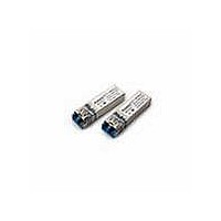
HFCT-5953TL
Description
Fiber Optic Transmitters, Receivers, Transceivers OC12 IR 2x5 SFF LC
Manufacturer
Avago Technologies US Inc.
Datasheet
1.HFCT-5953TL.pdf
(17 pages)
Specifications of HFCT-5953TL
Function
High performance, modules for serial optical data communication applications, designed for single mode fiber.
Product
Transceiver
Data Rate
622 Mbps
Wavelength
1300 nm
Maximum Rise Time
1 ns, 0.5 ns
Maximum Fall Time
1 ns, 0.5 ns
Maximum Output Current
50 mA
Operating Supply Voltage
3.14 V to 3.47 V
Maximum Operating Temperature
+ 70 C
Minimum Operating Temperature
0 C
Package / Case
DIP-10 with Connector
Optical Fiber Type
TX/RX
Data Transfer Rate
622Mbps
Optical Rise Time
1/0.5ns
Optical Fall Time
1/0.5ns
Operating Temperature Classification
Commercial
Peak Wavelength
1356/1570nm
Package Type
DIP With Connector
Operating Supply Voltage (min)
3.14V
Operating Supply Voltage (typ)
3.3V
Operating Supply Voltage (max)
3.47V
Output Current
50mA
Operating Temp Range
0C to 70C
Mounting
Snap Fit To Panel
Pin Count
10
For Use With
Singlemode Glass
Lead Free Status / RoHS Status
Lead free / RoHS Compliant


Recommended Cleaning/ Degreasing Chemicals
Alcohols: methyl, isopropyl, isobutyl.
Aliphatics: hexane, heptane
Other: naphtha.
Do not use partially halogenated hydrocarbons such as
1,1.1 trichloroethane, ketones such as MEK, acetone,
chloroform, ethyl acetate, methylene dichloride, phe-
nol, methylene chloride, or N-methylpyrolldone. Also,
Avago Technologies does not recommend the use of
cleaners that use halogenated hydrocarbons because of
their potential environmental harm.
LC SFF Cleaning Recommendations
In the event of contamination of the optical ports, the
recommended cleaning process is the use of forced ni-
trogen. If contamination is thought to have remained,
the optical ports can be cleaned using a NTT interna-
tional Cletop stick type (diam. 1.25 mm) and HFE7100
cleaning fluid.
Table 1: Regulatory Compliance - Targeted Specification
12
Regulatory Compliance
The Regulatory Compliance for transceiver performance
is shown in Table 1. The overall equipment design will
determine the certification level. The transceiver per-
formance is offered as a figure of merit to assist the de-
signer in considering their use in equipment designs.
Feature
Electrostatic Discharge
(ESD) to the
Electrical Pins
Electrostatic Discharge
(ESD) to the LC Receptacle
Electromagnetic
Interference (EMI)
Immunity
Laser Eye Safety
and Equipment Type
Testing
Component
Recognition
Test Method
MIL-STD-883
Method 3015
Variation of IEC 61000-4-2
FCC Class B
Variation of IEC 61000-4-3
FDA CDRH 21-CFR 1040
Class 1
IEC 60825-1
Amendment 2 2001-01
Underwriters Laboratories and
Canadian Standards Association Joint
Component Recognition
for Information Technology
Equipment Including Electrical
Business Equipment.
Electrostatic Discharge (ESD)
There are two design cases in which immunity to ESD
damage is important.
The first case is during handling of the transceiver prior
to mounting it on the circuit board. It is important to
use normal ESD handling precautions for ESD sensitive
devices. These precautions include using grounded
wrist straps, work benches, and floor mats in ESD con-
trolled areas.
The second case to consider is static discharges to the
exterior of the equipment chassis containing the trans-
ceiver parts. To the extent that the LC connector recep-
tacle is exposed to the outside of the equipment chassis
it may be subject to whatever system-level ESD test
criteria that the equipment is intended to meet.
Electromagnetic Interference (EMI)
Most equipment designs utilizing these high-speed
transceivers from Avago Technologies will be required
to meet FCC regulations in the United States, CENELEC
EN55022 (CISPR 22) in Europe and VCCI in Japan. Refer
to EMI section (page 9) for more details.
Immunity
Transceivers will be subject to radio-frequency electro-
magnetic fields following the IEC 61000-4-3 test method.
Performance
Class 2 (>2 kV).
Tested to 8 kV contact discharge.
Margins are dependent on customer board and chassis
designs.
Typically show no measurable effect from a
10 V/m field swept from 27 to 1000 MHz applied to the
transceiver without a chassis enclosure.
Accession Number: ) 9521220-43
License Number: ) 933/510104/02
UL File. E173874
Related parts for HFCT-5953TL
Image
Part Number
Description
Manufacturer
Datasheet
Request
R

Part Number:
Description:
TXRX SMF XFP 10BGE 2KM OC-192
Manufacturer:
Avago Technologies US Inc.
Datasheet:

Part Number:
Description:
Fiber Optic Transmitters, Receivers, Transceivers OC3 SFP IR -10 to +8 5 non-DMI
Manufacturer:
Avago Technologies US Inc.
Datasheet:

Part Number:
Description:
Fiber Optics, Transceiver Module
Manufacturer:
Avago Technologies US Inc.
Part Number:
Description:
Fiber Optic Transmitters, Receivers, Transceivers SFP OC12 IR Standard Delatch
Manufacturer:
Avago Technologies US Inc.

Part Number:
Description:
Manufacturer:
Avago Technologies
Datasheet:

Part Number:
Description:
155 Mb/s Single Mode Laser Transceiver For Atm, Sonet OC-3/SDH STM-1 (L1.1)
Manufacturer:
Agilent Technologies, Inc.
Datasheet:
Part Number:
Description:
Fiber Optics, Evaluation Kit
Manufacturer:
Avago Technologies US Inc.
Datasheet:
Part Number:
Description:
Fiber Optics, Evaluation Kit
Manufacturer:
Avago Technologies US Inc.
Datasheet:
Part Number:
Description:
Fiber Optics, Evaluation Kit
Manufacturer:
Avago Technologies US Inc.
Datasheet:

Part Number:
Description:
Agilent HFCT-5215B/D 155 Mb/s Single Mode Laser Transceiver
Manufacturer:
Hewlett-Packard
Datasheet:

Part Number:
Description:
OPTOCOUPLER GATE DRV 2A 16-SOIC
Manufacturer:
Avago Technologies US Inc.
Datasheet:
Part Number:
Description:
OPTOCOUPLER 2CH 2.5A 16-SOIC
Manufacturer:
Avago Technologies US Inc.
Datasheet:

Part Number:
Description:
OPTOCOUPLER GATE DRV 0.4A 16SOIC
Manufacturer:
Avago Technologies US Inc.
Datasheet:

Part Number:
Description:
OPTOCOUPLER 2.0A 250KHZ 8-DIP
Manufacturer:
Avago Technologies US Inc.
Datasheet:

Part Number:
Description:
OPTOCOUPLER 2.0A 250KHZ GW 8-SMD
Manufacturer:
Avago Technologies US Inc.
Datasheet: