5536501-1 TE Connectivity, 5536501-1 Datasheet

HARD METRIC CONNECTOR, HEADER, 24POS

5536501-1

Manufacturer Part Number
5536501-1
Description
HARD METRIC CONNECTOR, HEADER, 24POS
Manufacturer
TE Connectivity
Type
Backplaner
Series
Z-PACKr
Datasheets

Specifications of 5536501-1

Pitch (mm)
2mm
Gender
HDR
Body Orientation
Straight
Number Of Contact Rows
4
Number Of Contacts
24POS
Termination Method
Solder
Mounting Style
Through Hole
Contact Plating
Gold
Voltage Rating Max
30VAC
Contact Material
Phosphor Bronze
Housing Material
Liquid Cryst Polymer
Product Height (mm)
17mm
Product Depth (mm)
15.8mm
Product Length (mm)
11.88mm
Connector Type
Backplane
Row Pitch
2mm
Pitch Spacing
2mm
No. Of Contacts
24
Contact Termination
Through Hole
No. Of Rows
4
Rohs Compliant
Yes
Number Of Rows
4
Number Of Positions / Contacts
24
Pitch
2 mm
Termination Style
Solder
Product Type
Connector
Pcb Mounting Orientation
Vertical
Post Type
Solder Post
Module Type
Signal
Mating Post Length (mm [in])
6.50 [0.256]
Pin Header Width (mm [in])
16.00 [0.622]
Voltage Rating (vac)
30
Termination Post Length (mm [in])
4.25 [0.167]
Number Of Signal Positions
24
Sequencing
No
Post Plating
Tin
Centerline, Matrix (mm [in])
2.00 x 2.00 [.079 x .079]
Contact Type
Pin
Contact Base Material
Phosphor Bronze
Contact Plating, Mating Area, Material
Gold (30)
Connector Style
Plug
Rohs/elv Compliance
RoHS compliant, ELV compliant
Lead Free Solder Processes
Wave solder capable to 240°C, Wave solder capable to 260°C, Wave solder capable to 265°C, Reflow solder capable to 245°C, Reflow solder capable to 260°C, Pin-in-Paste capable to 245°C, Pin-in-Paste capable to 260°C
Rohs/elv Compliance History
Always was RoHS compliant
Applies To
Printed Circuit Board
Application
Fixed-Board
Lead Free Status / RoHS Status
Compliant
1.
1.1.
1.2.
2.
2.1.
3.
3.1.
3.2.
©2011 Tyco Electronics Corporation,
a TE Connectivity Ltd. Company
All Rights Reserved
TE logo is a trademark.
SCOPE
Content
This specification covers performance, tests and quality requirements for the Z-PACK* 2mm FB
connector system. This connector system is a backplane bus system which interconnects printed circuit
boards using pin and receptacle connectors. Connectors employ a four row 2mm centerline
configuration. Being through hole devices, pin and receptacle contacts have either solder or press fit
leads.
Qualification
When tests are performed on the subject product line, procedures specified in 109 Series Test
Specifications shall be used. All inspections shall be performed using the applicable inspection plan and
product drawing.
APPLICABLE DOCUMENTS
The following documents form a part of this specification to the extent specified herein. Unless
otherwise specified, the latest edition of the document applies. In the event of conflict between
requirements of this specification and the product drawing, the product drawing shall take precedence.
In the event of conflict between requirements of this specification and referenced documents, this
specification shall take precedence.
TE Connectivity (TE) Documents
!
!
!
REQUIREMENTS
Design and Construction
Product shall be of design, construction and physical dimensions specified on the applicable product
drawing.
Materials
!
!
109-1: General Requirements for Test Specifications
109 Series: Test Specifications as indicated in Figure 1
501-334: Qualification Test Report
Contact:
Housing: High temperature thermoplastic, liquid crystal polymer
Signal/power pin: Phosphor bronze, gold over palladium nickel over nickel plating
Signal receptacle: Copper nickel zinc, gold over palladium nickel over nickel plating
Power receptacle: Beryllium copper, gold over palladium nickel over nickel plating
| Indicates change
*Trademark
Product
Specification
Connector, Z-PACK*, 2 mm FB, Signal and Power
For latest revision, visit our website at www.te.com/documents.
For Regional Customer Service, visit our website at www.te.com
Other products, logos, and company names might be trademarks of their respective owners.
108-1441
11Mar11 Rev C
1 of 8
LOC B

Related parts for 5536501-1

5536501-1 Summary of contents

Page 1

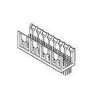
... Power receptacle: Beryllium copper, gold over palladium nickel over nickel plating ! Housing: High temperature thermoplastic, liquid crystal polymer ©2011 Tyco Electronics Corporation, | Indicates change a TE Connectivity Ltd. Company *Trademark All Rights Reserved TE logo is a trademark. For latest revision, visit our website at www.te.com/documents. ...

Page 2

Ratings ! Voltage: 30 volts alternating current ! Current: • Power: 3 amperes per contact • Signal: See Figure 5 for applicable current carrying capability ! Temperature: -55 to 125° Maximum Initial Contact Resistance: See Figure 1 ...

Page 3

Test Description Vibration, sinusoidal. Physical shock. Durability. Mating force. Unmating force. Thermal shock. Humidity-temperature cycling. Rev C Requirement MECHANICAL No discontinuities of 1 microsecond or longer duration. See Note. No discontinuities of 1 microsecond or longer duration. See Note. See ...

Page 4

Test Description Temperature life. Mixed flowing gas. Shall meet visual requirements, show no physical damage and shall meet requirements of NOTE additional tests as specified in Test Sequence in Figure 3. Rev C Requirement See Note. See Note. Figure 2 ...

Page 5

Product Qualification and Requalification Test Sequence Test or Examination Examination of product Termination resistance Insulation resistance Dielectric withstanding voltage Temperature rise vs current Vibration Physical shock Durability Mating force Unmating force Thermal shock Humidity-temperature cycling Temperature life Mixed flowing ...

Page 6

Power connectors. Power connector housings and contacts shall be prepared in accordance with applicable Instruction Sheets and shall be selected at random from current production. All test groups shall consist of 5 connectors each of the largest available size. ...

Page 7

To determine acceptable current carrying capacity for percentage connector loading, use the NOTE Multiplication Factor (F) from the above chart and multiply it times Base Rated Current for a single circuit at maximum ambient operating temperature as shown in Figure ...

Page 8

Rev C Figure 6 Vibration & Physical Shock Mounting Fixture 108-1441 ...

Related keywords