GBPC2502W Vishay, GBPC2502W Datasheet - Page 3
GBPC2502W
Manufacturer Part Number
GBPC2502W
Description
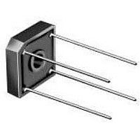
Bridge Rectifiers 200 Volt 25 Amp
Manufacturer
Vishay
Specifications of GBPC2502W
Product
Single Phase Bridge
Peak Reverse Voltage
200 V
Maximum Rms Reverse Voltage
140 V
Max Surge Current
300 A
Forward Voltage Drop
1.1 V
Maximum Reverse Leakage Current
5 uA
Maximum Operating Temperature
+ 150 C
Length
28.8 mm
Width
28.8 mm
Height
7.62 mm
Mounting Style
Through Hole
Minimum Operating Temperature
- 55 C
Package / Case
GBPC-W
No. Of Phases
Single
Repetitive Reverse Voltage Vrrm Max
200V
Forward Current If(av)
25A
Forward Voltage Vf Max
1.1V
Diode Mounting Type
Through Hole
Phase Type
Single Phase
Number Of Elements
1
Peak Rep Rev Volt
200V
Rms Voltage (max)
140V
Peak Non-repetitive Surge Current (max)
300A
Avg. Forward Curr (max)
25A
Rev Curr
5uA
Forward Voltage
1.1V
Package Type
Case GBPC-W
Operating Temp Range
-55C to 150C
Pin Count
4
Mounting
Screw
Operating Temperature Classification
Military
Lead Free Status / RoHS Status
Lead free / RoHS Compliant
Lead Free Status / RoHS Status
Lead free / RoHS Compliant, Lead free / RoHS Compliant
Available stocks
Company
Part Number
Manufacturer
Quantity
Price
Company:

Part Number:
GBPC2502W
Manufacturer:
Fairchild Semiconductor
Quantity:
135
Company:
Part Number:
GBPC2502W-E4/51
Manufacturer:
Vishay Semiconductors
Quantity:
135


RATINGS AND CHARACTERISTICS CURVES
(T
Document Number: 88612
Revision: 15-Apr-08
A
= 25 °C unless otherwise noted)
40
35
30
25
20
15
10
80
70
60
50
40
30
20
10
40
35
30
25
20
15
10
5
0
5
0
0
0
0
0
Figure 1. Maximum Output Rectified Current
Figure 2. Maximum Output Rectified Current
GBPC35
R
GBPC25
R
GBPC15
R
GBPC12
R
60 Hz
Resistive or
Inductive Load
thSA
thSA
thSA
thSA
10
T
Figure 3. Maximum Power Dissipation
25
J
Capacitive Load
= 0.5 °C/W
= 0.5 °C/W
= 1.0 °C/W
= 1.0 °C/W
= T
20
J
Max.
50
Average Output Current (A)
10
Ambient Temperature (°C)
30
Case Temperature (°C)
75
40
Bridges Mounted on
9.5 x 3.5 x 4.6"
(22.9 x 8.9 x 11.7 cm)
AL, Finned Plate
PDD-Americas@vishay.com, PDD-Asia@vishay.com, PDD-Europe@vishay.com
100
50
For technical questions within your region, please contact one of the following:
20
5 x 6 x 4.9"
AL, Finned Plate
5 x 4 x 3"
AL, Finned Plate
60
125
Resistive or
Inductive Load
70
6 x 2.2 x 2.2"
AL, Finned Plate
60 Hz
Resistive or
Inductive Load
150
30
80
175
90
100
200
40
GBPC12, GBPC15, GBPC25 & GBPC35
Figure 5. Typical Instantaneous Forward Characteristics Per Diode
Figure 6. Typical Reverse Leakage Characteristics Per Diode
Figure 4. Maximum Non-Repetitive Peak Forward Surge
1000
1000
100
100
100
0.1
0.1
10
10
10
1
1
0.4
1
0
Vishay General Semiconductor
Percent of Rated Peak Reverse Voltage (%)
T
10
A
0.5
= 100 °C
Instantaneous Forward Voltage (V)
20
T
Number of Cycles at 60 Hz
A
0.6
= 125 °C
30
Current Per Diode
1.0 Cycle
T
40
A
0.7
= 150 °C
T
T
T
T
A
A
A
A
10
50
= 125 °C
= 150 °C
= 100 °C
= 25 °C
T
0.5 ms Single Sine-Wave
0.8
J
= T
60
GBPC12
J
Max.
70
0.9
GBPC35
T
A
80
= 25 °C
GBPC15
GBPC25
1.0
90
www.vishay.com
100
100
1.1
3
Related parts for GBPC2502W
Image
Part Number
Description
Manufacturer
Datasheet
Request
R


Part Number:
Description:
357-036-542-201 CARDEDGE 36POS DL .156 BLK LOPRO
Manufacturer:
Vishay
Datasheet:
Part Number:
Description:
357-036-542-201 CARDEDGE 36POS DL .156 BLK LOPRO
Manufacturer:
Vishay
Datasheet:
Part Number:
Description:
357-036-542-201 CARDEDGE 36POS DL .156 BLK LOPRO
Manufacturer:
Vishay
Datasheet:
Part Number:
Description:
357-036-542-201 CARDEDGE 36POS DL .156 BLK LOPRO
Manufacturer:
Vishay
Datasheet:
Part Number:
Description:
357-036-542-201 CARDEDGE 36POS DL .156 BLK LOPRO
Manufacturer:
Vishay
Datasheet:
Part Number:
Description:
357-036-542-201 CARDEDGE 36POS DL .156 BLK LOPRO
Manufacturer:
Vishay
Datasheet:
Part Number:
Description:
357-036-542-201 CARDEDGE 36POS DL .156 BLK LOPRO
Manufacturer:
Vishay
Datasheet:
Part Number:
Description:
357-036-542-201 CARDEDGE 36POS DL .156 BLK LOPRO
Manufacturer:
Vishay
Datasheet:
Part Number:
Description:
357-036-542-201 CARDEDGE 36POS DL .156 BLK LOPRO
Manufacturer:
Vishay
Datasheet:
Part Number:
Description:
357-036-542-201 CARDEDGE 36POS DL .156 BLK LOPRO
Manufacturer:
Vishay
Datasheet:
Part Number:
Description:
357-036-542-201 CARDEDGE 36POS DL .156 BLK LOPRO
Manufacturer:
Vishay
Datasheet:
Part Number:
Description:
357-036-542-201 CARDEDGE 36POS DL .156 BLK LOPRO
Manufacturer:
Vishay
Datasheet:
Part Number:
Description:
357-036-542-201 CARDEDGE 36POS DL .156 BLK LOPRO
Manufacturer:
Vishay
Datasheet:
Part Number:
Description:
357-036-542-201 CARDEDGE 36POS DL .156 BLK LOPRO
Manufacturer:
Vishay
Datasheet: