AD6635BB Analog Devices Inc, AD6635BB Datasheet - Page 46
AD6635BB
Manufacturer Part Number
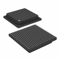
AD6635BB
Description
IC,RF/Baseband Circuit,CMOS,BGA,324PIN,PLASTIC
Manufacturer
Analog Devices Inc
Series
AD6635r
Datasheet
1.AD6635BBPCB.pdf
(60 pages)
Specifications of AD6635BB
Rohs Status
RoHS non-compliant
Rf Type
Cellular, CDMA2000, EDGE, GPRS, GSM
Number Of Mixers
1
Current - Supply
880mA
Voltage - Supply
3 V ~ 3.6 V
Package / Case
324-BGA
Frequency
-
Gain
-
Noise Figure
-
Secondary Attributes
-
Lead Free Status / RoHS Status
Available stocks
Company
Part Number
Manufacturer
Quantity
Price

Part Number:
AD6635BB
Manufacturer:
ADI/亚德诺
Quantity:
20 000


AD6635
Bit 5 determines the word length used by the parallel port. If
this bit is 0, the parallel port uses 12-bit words for I and Q. If
this bit is 1, the parallel port uses 16-bit words for I and Q.
When the fixed-point output option is chosen from the RCF
control register, these bits also set the rounding correctly in the
output formatter of the RCF.
The remaining bits in this register are reserved and should be
written low when programming.
In order to access the Input Port registers, the Access Input/
Output Control registers bit (Bit 5) of the Sleep register (exter-
nal address 0x3) should be set. The CAR (Channel Address
register, external address 0x6) is then written with the address
to the correct Input Port register.
For Channels 0 to 3 and Input Ports A and B, Chip Select 0
(CS0) should be used while programming using the microport.
Similarly for Channels 4 to 7 and Input Ports C and D, Chip
Select 1 (CS1) should be used while programming using the
microport.
Note: For the registers in Table XIV, Input Ports A and B
should be duplicated with Input Ports C and D when Chip
Select 1 (CS1) is used instead of (CS0) while programming the
microport. Similarly, Channels 0 to 3 should also be duplicated
with Channels 4 to 7 wherever mentioned.
Input Port Control Registers
The input port control register enables various input related
features used primarily for input detection and level control.
Depending on the mode of operation, up to four different signal
paths can be monitored with these registers. These features are
accessed by setting Bit 5 of external address 3 (Sleep register)
and then using the CAR (external address 6) to address the
eight locations available.
Response to these settings is directed to the LIA-A, LIA-B,
LIB-A, and LIB-B pins.
0x00 Lower Threshold A
This word is 10 bits wide and maps to the 10 most significant
bits of the mantissa. If the upper 10 bits of Input Port A are less
than or equal to this value, the lower threshold has been met. In
Channel Address
00
01
02
03
04
05
06
07
Lower Threshold A
Upper Threshold A
Dwell Time A
Gain Range A Control Register
Lower Threshold B
Upper Threshold B
Dwell Time B
Gain Range B Control Register
Register
Table XIV. Memory Map for Input Port Control Registers
Bit Width
10
10
20
5
10
10
20
5
–46–
normal chip operation, this starts the dwell time counter. If the
input signal increases above this value then the counter is re-
loaded and waits for the input to drop back to this level.
0x01 Upper Threshold A
This word is 10 bits wide and maps to the 10 MSBs of the
mantissa. If the upper 10 bits of Input Port A are greater than
or equal to this value, the upper threshold has been met. In
normal chip operation, this will cause the appropriate LI pin
(LIA-A or LIA-B) to become active.
0x02 Dwell Time A
This sets the time that the input signal must be at or below the
lower threshold before the LI pin is deactivated. For the input
level detector to work, the dwell time must be set to at least 1.
If set to 0, the LI functions are disabled.
This is a 20-bit register. When the lower threshold is met fol-
lowing an excursion into the upper threshold, the dwell time
counter is loaded and begins to count high speed clock cycles as
long as the input is at or below the lower threshold. If the signal
increases above the lower threshold, the counter is reloaded and
waits for the signal to fall below the lower threshold again.
0x03 Gain Range A Control Register
Bit 4 determines the polarity of LIA-A and LIA-B. If this bit is
clear, the LI signal is high when the upper threshold has been
exceeded. However, if this bit is set, the LI pin is low when active.
This allows maximum flexibility when using this function.
Bit 3 determines if the input consists of a single channel or
TDM channels, such as when using the AD6600. If this bit is
cleared, a single ADC is assumed. In this mode, LIA-A func-
tions as the active output indicator. LIA-B provides the
compliment of LIA-A. However, if this bit is set, the input is
determined to be dual channel and determined by the state of
the IENA pin. If the IENA pin is low, the input detection is
directed to LIA-A. If the IENA pin is high, the input is directed
to LIA-B. In either case, Bit 4 determines the actual polarity of
these signals.
Bits 2–0 determine the internal latency of the gain detect func-
tion. When the LIA-A and LIA-B pins are made active, they are
typically used to change an attenuator or gain stage. Since this
Comments
9–0: Lower Threshold for Input A
9–0: Upper Threshold for Input A
19–0: Minimum Time below Lower Threshold A
4: Output Polarity LIA-A and LIA-B
3: Interleaved Channels
2–0: Linearization Holdoff Register
9–0: Lower Threshold for Input B
9–0: Upper Threshold for Input B
19–0: Minimum Time below Lower Threshold B
4: Output Polarity LIB-A and LIB-B
3: Interleaved Channels
2–0: Linearization Holdoff Register
REV. 0
Related parts for AD6635BB
Image
Part Number
Description
Manufacturer
Datasheet
Request
R

Part Number:
Description:
±1.7g Dual-Axis IMEMS Accelerometer Evaluation Board
Manufacturer:
Analog Devices Inc
Datasheet:

Part Number:
Description:
Inertial Sensor Evaluation System
Manufacturer:
Analog Devices Inc
Datasheet:
Part Number:
Description:
Manufacturer:
Analog Devices Inc
Datasheet:
Part Number:
Description:
Manufacturer:
Analog Devices Inc
Datasheet:
Part Number:
Description:
Manufacturer:
Analog Devices Inc
Datasheet:
Part Number:
Description:
Manufacturer:
Analog Devices Inc
Datasheet:
Part Number:
Description:
Manufacturer:
Analog Devices Inc
Datasheet:
Part Number:
Description:
Manufacturer:
Analog Devices Inc
Datasheet:
Part Number:
Description:
Manufacturer:
Analog Devices Inc
Datasheet:
Part Number:
Description:
Manufacturer:
Analog Devices Inc
Datasheet:
Part Number:
Description:
Manufacturer:
Analog Devices Inc
Datasheet:
Part Number:
Description:
Manufacturer:
Analog Devices Inc
Datasheet:
Part Number:
Description:
Manufacturer:
Analog Devices Inc
Datasheet: