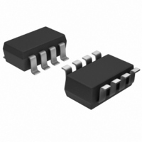
AD8034ART-REEL7 Analog Devices Inc, AD8034ART-REEL7 Datasheet - Page 21

AD8034ART-REEL7
Manufacturer Part Number
AD8034ART-REEL7
Description
IC,Operational Amplifier,DUAL,BIPOLAR/JFET,TSSOP,8PIN,PLASTIC
Manufacturer
Analog Devices Inc
Series
FastFET™r
Datasheet
1.AD8033AKSZ-REEL7.pdf
(24 pages)
Specifications of AD8034ART-REEL7
Rohs Status
RoHS non-compliant
Amplifier Type
Voltage Feedback
Number Of Circuits
2
Output Type
Rail-to-Rail
Slew Rate
80 V/µs
-3db Bandwidth
80MHz
Current - Input Bias
1.5pA
Voltage - Input Offset
1000µV
Current - Supply
3.3mA
Current - Output / Channel
60mA
Voltage - Supply, Single/dual (±)
5 V ~ 24 V, ±2.5 V ~ 12 V
Operating Temperature
-40°C ~ 85°C
Mounting Type
Surface Mount
Package / Case
SOT-23-8
Gain Bandwidth Product
-
Lead Free Status / RoHS Status
When selecting components, the common-mode input capacitance
must be taken into consideration.
Filter cutoff frequencies can be increased beyond 1 MHz using the
AD8033/AD8034 but limited open-loop gain and input impedance
begin to interfere with the higher Q stages. This can cause early
roll-off of the overall response.
Additionally, the stop-band attenuation decreases with decreasing
open-loop gain.
Keeping these limitations in mind, a 2-pole Sallen-Key Butterworth
filter with f
low Q of 0.707 while still maintaining 15 dB of attenuation an
octave above f
and response are shown in Figure 60 and Figure 61, respectively.
–10
–15
–20
–25
–30
–35
–40
–45
–5
V
5
0
100k
IN
Figure 61. 2-Pole Butterworth Active Filter Response
C
= 4 MHz can be constructed that has a relatively
R5
49.9Ω
C
Figure 60. 2-Pole Butterworth Active Filter
and 35 dB of stop-band attenuation. The filter
2.49kΩ
22pF
R1
C3
1M
2.49kΩ
FREQUENCY (Hz)
R2
10pF
C1
AD8033
10M
+V
–V
S
S
V
OUT
100M
Rev. D | Page 21 of 24
WIDEBAND PHOTODIODE PREAMP
Figure 62 shows an I/V converter with an electrical model of a
photodiode.
The basic transfer function is
where I
parallel combination of R
The stable bandwidth attainable with this preamp is a function
of R
capacitance at the summing junction of the amplifier, including
C
produce a pole in the loop transmission of the amplifier that
can result in peaking and instability. Adding C
in the loop transmission that compensates for the effect of the
pole and reduces the signal bandwidth. It can be shown that the
signal bandwidth resulting in a 45°phase margin (f
by the expression
where:
f
R
C
(amplifier + photodiode + board parasitics).
The value of C
The frequency response in this case shows about 2 dB of
peaking and 15% overshoot. Doubling C
bandwidth in half results in a flat frequency response, with
about 5% transient overshoot.
I
PHOTO
CR
F
S
S
and the amplifier input capacitance. R
is the feedback resistor.
is the total capacitance at the amplifier summing junction
is the amplifier crossover frequency.
F
, the gain bandwidth product of the amplifier, and the total
V
C
f
(
OUT
V
F
45
PHOTO
B
)
=
=
=
is the output current of the photodiode, and the
2
I
2
π
1
PHOTO
F
Figure 62. Wideband Photodiode Preamp
C
π
+
×
that produces f
S
C
F
×
sC
R
C
+ C
R
f
F
S
F
CR
×
S
F
×
R
R
×
F
f
F
R
C
CR
F
SH
S
and C
= 10
11
(45)
Ω
R
F
F
sets the signal bandwidth.
is
AD8033/AD8034
C
F
D
and the total capacitance
F
and cutting the
C
C
M
M
C
R
F
F
F
creates a zero
(45)
) is defined
V
OUT


