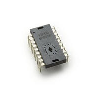
ADNS-5000 Avago Technologies US Inc., ADNS-5000 Datasheet - Page 15

ADNS-5000
Manufacturer Part Number
ADNS-5000
Description
IC USB OPT MOUSE SENSOR 18-DIP
Manufacturer
Avago Technologies US Inc.
Datasheet
1.ADNS-5000.pdf
(34 pages)
Specifications of ADNS-5000
Product
Optical
Lead Free Status / RoHS Status
Lead free / RoHS Compliant
Lead Free Status / RoHS Status
Lead free / RoHS Compliant, Lead free / RoHS Compliant
X & Y Directions
(Looking through an ADNS-5100 Lens)
The positive and negative X and Y directions with respect
to the mouse case are shown in the diagram below.
Figure 18. Directions are for a complete mouse, with the ADNS-5100 lens
XY LED
x The peak current values are 30 mA if R1 59ohm and
Buttons
The minimum time between button presses is T
tons B1 through B3 are connected to a Schmidt trigger
input with 100 uA current sources pulling up to +5 volts
during normal, sleep and USB suspend modes.
15
the part meets the IEC 825-1 eye safety regulations.
O
S
T
V
P
E
Y
I
I
Top Xray View of Mouse
LB
9
1
POSITIVE X
xxxx
RB
18
10
DBB
. But-
Z-Wheel
The mechanical Z-Wheel connections (A,B) are deter-
mined below.
Figure 19. Z-Wheel A and B connections
Notes:
For mechanical Z-wheels the following must be imple-
mented:
x Use a rotary switch equivalent to the Panasonic part
x Solder the rotary switch into the PCB such that the
x Connect the “A” terminal of the rotary switch to “ZA”
EVQVX at http://industrial.panasonic.com/www-
data/pdf/ATC0000/ATC0000CE20.pdf (The key point
is stable “A” switch state in all detent positions).
common pin is closest to the cable end of the mouse.
(Metal plate faces to left)
and the “B” terminal to “ZB”. ZA MUST be connected
to “Signal A” in Figure 19 where the z-wheel detents
are mechanically stable.


