MBR3045PT ON Semiconductor, MBR3045PT Datasheet

DIODE SCHOTTKY 45V 15A SOT93

MBR3045PT

Manufacturer Part Number
MBR3045PT
Description
DIODE SCHOTTKY 45V 15A SOT93
Manufacturer
ON Semiconductor
Series
SWITCHMODE™r
Datasheet

Specifications of MBR3045PT

Voltage - Forward (vf) (max) @ If
760mV @ 30A
Current - Reverse Leakage @ Vr
1mA @ 45V
Current - Average Rectified (io) (per Diode)
15A
Voltage - Dc Reverse (vr) (max)
45V
Diode Type
Schottky
Speed
Fast Recovery =< 500ns, > 200mA (Io)
Diode Configuration
1 Pair Common Cathode
Mounting Type
Through Hole, Radial
Package / Case
SOT-93, TO-218 (Straight Leads)
Lead Free Status / RoHS Status
Contains lead / RoHS non-compliant
Reverse Recovery Time (trr)
-
Other names
MBR3045PTOS

Available stocks

Company
Part Number
Manufacturer
Quantity
Price
Part Number:
MBR3045PT
Manufacturer:
GI
Quantity:
320
Part Number:
MBR3045PT
Manufacturer:
GI
Quantity:
5 006
Part Number:
MBR3045PT
Manufacturer:
VISHAY
Quantity:
36
Part Number:
MBR3045PT
Manufacturer:
ON Semiconductor
Quantity:
42
Part Number:
MBR3045PT
Manufacturer:
ST
0
Part Number:
MBR3045PT
Manufacturer:
MOTOROLA/摩托罗拉
Quantity:
20 000
Company:
Part Number:
MBR3045PT
Quantity:
10
Company:
Part Number:
MBR3045PT
Quantity:
30
Part Number:
MBR3045PT-E3/45
Manufacturer:
VISHAY/威世
Quantity:
20 000
Company:
Part Number:
MBR3045PT-E3/45
Quantity:
3 000
Part Number:
MBR3045PTG
Manufacturer:
ON Semiconductor
Quantity:
1 938
Part Number:
MBR3045PTG
Manufacturer:
ON/安森美
Quantity:
20 000
Company:
Part Number:
MBR3045PTG
Quantity:
3 000
MBR3045PT
SWITCHMODEt
Power Rectifier
with a platinum barrier metal.
Features
Mechanical Characteristics
Maximum ratings are those values beyond which device damage can occur.
Maximum ratings applied to the device are individual stress limit values (not
normal operating conditions) and are not valid simultaneously. If these limits are
exceeded, device functional operation is not implied, damage may occur and
reliability may be affected.
1. The heat generated must be less than the thermal conductivity from
*For additional information on our Pb−Free strategy and soldering details, please
MAXIMUM RATINGS
February, 2006 − Rev. 3
download the ON Semiconductor Soldering and Mounting Techniques
Reference Manual, SOLDERRM/D.
Peak Repetitive Reverse Voltage
Working Peak Reverse Voltage
DC Blocking Voltage
Average Rectified Forward Current
(Rated V
Peak Repetitive Forward Current,
Non−Repetitive Peak Surge Current
Peak Repetitive Reverse Current (2.0 ms,
Storage Temperature Range
Operating Junction Temperature (Note 1)
Peak Surge Junction Temperature
Voltage Rate of Change (Rated V
These state−of−the−art devices use the Schottky Barrier principle
Parallel Operation at Full Rating
Leads are Readily Solderable
260 C Max. for 10 Seconds
Dual Diode Construction; Terminals 1 and 3 may be Connected for
Guard−ring for Stress Protection
Low Forward Voltage
175 C Operating Junction Temperature
Pb−Free Package is Available*
Case: Epoxy, Molded
Weight: 4.3 Grams (Approximately)
Finish: All External Surfaces Corrosion Resistant and Terminal
Lead Temperature for Soldering Purposes:
Semiconductor Components Industries, LLC, 2006
Junction−to−Ambient: dP
(Rated V
20 kHz) Per Diode
(Surge Applied at Rated Load Conditions
Halfwave, Single Phase, 60 Hz)
1.0 kHz) Per Diode (See Figure 6)
(Forward Current Applied)
R
, T
R
, Square Wave,
C
= 105 C)
Rating
D
/dT
Preferred Device
Per Device
J
Per Diode
< 1/R
R
)
qJA
.
Symbol
V
V
T
I
I
dv/dt
I
I
F(AV)
T
FRM
RRM
RWM
FSM
RRM
V
J(pk)
T
stg
R
J
−65 to +175
−65 to +175
10,000
Max
200
175
2.0
45
30
15
30
1
Unit
V/ms
V
A
A
A
A
C
C
C
Preferred devices are recommended choices for future use
and best overall value.
MBR3045PT
MBR3045PTG
1
2
Device
3
30 AMPERES, 45 VOLTS
SCHOTTKY BARRIER
ORDERING INFORMATION
http://onsemi.com
4
RECTIFIER
CASE 340D
1
3
PLASTIC
SOT−93
A
Y
WW
G
(Pb−Free)
Package
SOT−93
SOT−93
Publication Order Number:
= Assembly Location
= Year
= Work Week
= Pb−Free Package
2
4
30 Units / Rail
30 Units / Rail
MBR3045PT
MARKING
DIAGRAM
MBR3045PT/D
Shipping
AYWWG

Related parts for MBR3045PT

MBR3045PT Summary of contents

Page 1

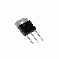
... PLASTIC Assembly Location Y = Year WW = Work Week G = Pb−Free Package ORDERING INFORMATION Device Package Shipping MBR3045PT SOT−93 30 Units / Rail MBR3045PTG SOT−93 30 Units / Rail (Pb−Free) Preferred devices are recommended choices for future use and best overall value. Publication Order Number: MBR3045PT/D ...

Page 2

... T = 150 5.0 3.0 2.0 1.0 0.5 0.3 0.2 0.1 0 0.2 0.4 0.6 0 INSTANTANEOUS FORWARD VOLTAGE (VOLTS) F Figure 1. Typical Forward Voltage MBR3045PT Rating (Per Diode) 2.0%. 100 10 1.0 0.1 0.01 1.0 1.2 1.4 0 http://onsemi.com 2 Symbol Max R 1.4 qJC R 40 qJA v F 0.60 ...

Page 3

... V , REVERSE VOLTAGE (VOLTS) R Figure 5. Capacitance MBR3045PT 20 (CAPACITIVE LOAD) 15 SQUARE WAVE 10 dc 5.0 0 130 140 150 160 0 5.0 I F(AV) Figure 4. Forward Power Dissipation (Per Leg 2 ...

Page 4

... Q 4.00 4.10 0.158 0.161 S 17.80 18.20 0.701 0.717 U 4.00 REF 0.157 REF V 1.75 REF 0.069 STYLE 1: PIN 1. BASE 2. COLLECTOR 3. EMITTER 4. COLLECTOR ON Semiconductor Website: http://onsemi.com Order Literature: http://www.onsemi.com/litorder For additional information, please contact your local Sales Representative. MBR3045PT/D ...

Related keywords