F3SP-B1P Omron, F3SP-B1P Datasheet - Page 23
F3SP-B1P
Manufacturer Part Number
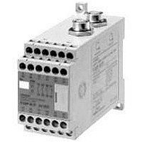
F3SP-B1P
Description
F3SN-A SAFETY RELAY UNIT
Manufacturer
Omron
Datasheet
1.F3SP-B1P.pdf
(27 pages)
Specifications of F3SP-B1P
Supply Voltage Max
24VDC
Light Curtain Type
Safety
Control Output Type
3NO/1NC
Lead Free Status / RoHS Status
Lead free / RoHS Compliant


Safety Precautions
Refer to “Regulations and Standards” and “Safety Precautions” for F3SN-A/F3SN-B/F3SH-A.
“Type Certification” specified in the Chapter 44. 2 of the Industrial Safety and Health Law in Japan does not apply to independent F3SS Sensors.
This law applies to systems incorporating the Sensor. When using the F3SL Sensor in Japan as a “safety device for presses or shearing machines,”
as specified in the Chapter 42 of the same law, apply for certification for the overall system.
Detection Zone and Intrusion Path
Use of the Fixed Blanking Function
Distance from Reflective Surfaces
Side View
Install the F3SN-A@SS using the minimum Distance D shown below
from reflective surfaces (highly reflective surfaces), such as metal
walls, floors, ceilings, and work pieces.
Install protective structures around the machine so that
you must pass through the detection zone of the F3SN-
A@SS to reach a hazardous part of the machine.
Install the F3SN-A@SS so that some part of the
operator’s body remains in the detection zone at all times
when the operator works in a hazardous area. Failure to
do so may result in serious injury.
Correct Installation
Incorrect Installation
Install protective structures in all parts of the detection
zone where detection is disabled by the fixed blanking
function so no one can pass through the detection zone
to reach the hazardous part of the machine. Failure to do
so may result in serious injury.
Be sure to install the F3SN-A@SS in a way that minimizes
the effects of reflection from nearby surfaces. Failure to
do so may cause detection to fail and may result in
serious injury.
Emitter
Reflecting ceiling
Detection zone
Reflecting floor
L
D
D
http://www.ia.omron.com/
A hazardous part
of a machine can
be reached only
by passing
through the
sensor detection
zone.
A hazardous part
of a machine can
be reached
without passing
through the
sensor detection
zone.
Receiver
!WARNING
Emitter
Top View
Correct Installation
Incorrect Installation
Reflecting surface
5°
L
D
5°
Some part of
the operator's
body remains in
the detection
zone while they
are working.
A worker is
between the
sensor
detection zone
and a
hazardous part
of a machine.
Receive
Safety Distance
The safety distance is the minimum distance that must be maintained
between the F3SN-A@SS and a hazardous part of a machine in
order to stop the machine before someone or something reaches it. It
is calculated based on the following equation when a person moves
perpendicular to the detection zone of a Light Curtain.
The safety distance varies with national standards and individual
machine standards. The equation is also different if the direction of
intrusion is not perpendicular to the detection zone of the Light
Curtain. Be sure to refer to related standards.
Refer to the “Safety Distance” and “Safety Precautions” for the
F3SN-A/F3SN-B, F3SH-A.
Installation
How to Prevent Mutual Interference
0.2 to 3 m
Over 3 m
Always maintain a safety distance (S) between the Light
Curtain and a hazardous part of a machine.
Failure to do so may prevent the machine from stopping
before an operator reaches the dangerous area and may
result in serious injury.
Floating blanking is used to increase the minimum
detectable object size. Be sure to use the minimum
detectable object size for floating blanking when
calculating safety distance. Failure to do so may prevent
the machine from stopping before an operator reaches
the dangerous area and may result in serious injury.
An Emitter and Receiver installed facing each other must
be a pair from the same set. The wrong combination may
create a zone where objects cannot be detected.
Do not use the Sensor for a reflected beam system, or
objects may not be detected. In those applications, use a
beam path diversion mirror to prevent any beam reflected
by an object from entering the Receiver.
Take necessary steps to prevent mutual interference
when installing two or more pairs of the F3SN-A@SS.
Examples of such steps include series connection and
the use of light baffle.
Safety distance (S) =Intrusion speed into the detection zone (K)
Distance between Emitter and
Receiver (operating range L)
(c)Copyright OMRON Corporation 2007 All Rights Reserved.
+ Additional distance calculated based on
Total response time for the machine and
Light Curtain (T)
the detection capability of the Light Curtain
(C)..........................................................(1)
0.13 m
L/2
Minimum installation distance D
tan 5 = L
F3SN-A@SS
0.044 (m)
23
Related parts for F3SP-B1P
Image
Part Number
Description
Manufacturer
Datasheet
Request
R


Part Number:
Description:
F3S-B OPTIONAL PROGRAMMING KIT
Manufacturer:
Omron
Datasheet:

Part Number:
Description:
G6S-2GLow Signal Relay
Manufacturer:
Omron Corporation
Datasheet:
Part Number:
Description:
Compact, Low-cost, SSR Switching 5 to 20 A
Manufacturer:
Omron Corporation
Datasheet:
Part Number:
Description:
Manufacturer:
Omron Corporation
Datasheet:
Part Number:
Description:
Manufacturer:
Omron Corporation
Datasheet:
Part Number:
Description:
Manufacturer:
Omron Corporation
Datasheet: