RS01AR5000FE74 Vishay, RS01AR5000FE74 Datasheet - Page 2
RS01AR5000FE74
Manufacturer Part Number
RS01AR5000FE74
Description
Manufacturer
Vishay
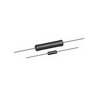
Type
Wirewoundr
Datasheet
1.RS01AR5000FE74.pdf
(3 pages)
Specifications of RS01AR5000FE74
Resistance Value
500 mOhm
Tolerance
1 %
Power Rating
1 W
Power Rating(s)
1W
Resistance
500mohm
Tolerance (+ Or -)
1%
Temperature Coefficient
±90
Termination Style
Axial
Operating Temp Range
-65C to 250C
Case Style
Ceramic Hi Temp Sil
Military Standard
MIL-PRF-26
Failure Rate
Not Required
Lead Spacing (nom)
Not Requiredmm
Product Length (mm)
11.1mm
Product Depth (mm)
Not Requiredmm
Product Height (mm)
Not Requiredmm
Construction
Cylindrical
Lead Free Status / Rohs Status
Compliant


DIMENSIONS in inches [millimeters]
Note
(1)
MATERIAL SPECIFICATIONS
Element: Copper-nickel alloy or nickel-chrome alloy,
depending on resistance value
Core: Ceramic, steatite or alumina, depending on physical
size
Coating: Special high temperature silicone
Standard Terminals: 100 % Sn, or 60/40 Sn/Pb coated
Copperweld
End Caps: Stainless steel
Part Marking: DALE, model, wattage
date code
Note
(2)
DERATING
Document Number: 30204
Revision: 24-Jan-11
TECHNICAL SPECIFICATIONS
PARAMETER
Temperature Coefficient
Maximum Working Voltage
Insulation Resistance
Operating Temperature Range
PERFORMANCE
TEST
Thermal Shock
Short Time Overload
Dielectric Withstanding
Voltage
Low Temperature Storage
High Temperature Exposure
Moisture Resistance
Shock, Specified Pulse
Vibration, High Frequency
Load Life
Terminal Strength
On some standard reel pack methods, the leads may be
trimmed to a shorter length than shown
Wattage marked on part will be “U” characteristic
120
100
80
60
40
20
0
- 65 - 50
®
0
25
50
Rated power applied until thermally stable, then a minimum of 15 min at - 55 °C
5 x rated power (3.75 W and smaller), 10 x rated power (4 W and larger) for 5 s
500 V
- 65 °C for 24 h
250 h at: U = + 250 °C, V = + 350 °C
MIL-STD-202 Method 213, 100 g’s for 6 ms, 10 shocks
Frequency varied 10 Hz to 2000 Hz, 20 g peak, 2 directions 6 h each
2000 h at rated power, + 25 °C, 1.5 h “ON”, 0.5 h “OFF”
Pull test 5 s to 10 s, 5 lb (RS1/4 thru RS01A), 10 lb for all others;
torsion test - 3 alternating directions, 360° each
MIL-STD-202 Method 106, 7b not applicable
A
B
RMS
CHAR. U
150
ppm/°C
AMBIENT TEMPERATURE IN °C
min. for RS1/4 thru RS01A, 1000 V
UNIT
°C
For technical questions, contact:
V
(2)
C
Precision Power, Silicone Coated
, value, tolerance,
Wirewound Resistors, Industrial,
1.50
[38.10]
min.
250
CHAR. V
CONDITIONS OF TEST
(1)
D
± 20 for 10 and above, ± 50 for 1 to 9.9 , ± 90 for below 1
Characterisitic U = - 65 to + 250, characteristic V = - 65 to + 350
350
1000 M minimum dry, 100 M minimum after moisture test
RMS
for all others, duration of 1 min
ww2bresistors@vishay.com
Note
(3)
NS NON-INDUCTIVE
Models of equivalent physical and electrical specifications
are available with non-inductive (Aryton-Perry) winding.
They are identified by substituting the letter N for R in the
model number (NS005, for example).
Two conditions apply:
1. For NS models, divide maximum resistance values by two
2. Body O.D. on NS02C may exceed that of the RS02C by
RS RESISTOR CHARACTERISTICS
GLOBAL
MODEL
RS1/4
RS1/2
RS01A
RS01A...300
RS01M
RS002
RS02M
RS02B
RS02B...300
RS02C
RS02C...17
RS02C...23
RS005
RS005...69
RS005...70
RS007
RS010
RS010...39
RS010...38
B (max.) dimension is clean lead to clean lead
010"
[10.31 ± 0.787]
0.250 ± 0.031
[6.35 ± 0.787]
0.312 ± 0.016
[7.92 ± 0.406]
0.285 ± 0.025
[7.24 ± 0.635]
0.625 ± 0.062
[15.88 ± 1.57]
0.500 ± 0.062
[12.70 ± 1.57]
0.560 ± 0.062
[14.22 ± 1.57]
0.500 ± 0.062
[12.70 ± 1.57]
0.500 ± 0.062
[12.70 ± 1.57]
0.875 ± 0.062
[22.23 ± 1.57]
[30.99 ± 1.57]
[45.21 ± 1.57]
[45.21 ± 1.57]
0.406 ± 0.031
1.22 ± 0.062
1.78 ± 0.062
1.78 ± 0.062
(P x R)
A
DIMENSIONS in inches [millimeters]
1/2
CHARACTERISTIC U CHARACTERISTIC V
± (0.2 % + 0.05 ) R ± (2.0 % + 0.05 ) R
± (0.2 % + 0.05 ) R ± (2.0 % + 0.05 ) R
± (0.1 % + 0.05 ) R ± (0.1 % + 0.05 ) R
± (0.2 % + 0.05 ) R ± (2.0 % + 0.05 ) R
± (0.5 % + 0.05 ) R ± (2.0 % + 0.05 ) R
± (0.2 % + 0.05 ) R ± (2.0 % + 0.05 ) R
± (0.1 % + 0.05 ) R ± (0.2 % + 0.05 ) R
± (0.1 % + 0.05 ) R ± (0.2 % + 0.05 ) R
± (0.5 % + 0.05 ) R ± (3.0 % + 0.05 ) R
± (0.1 % + 0.05 ) R ± (1.0 % + 0.05 ) R
(max.)
[11.10]
[19.43]
[14.27]
[15.80]
[15.06]
[15.06]
[32.51]
[47.50]
[46.74]
0.281
[7.14]
0.328
[8.33]
0.437
0.311
[7.90]
0.765
0.562
0.622
0.593
0.593
[25.4]
B
1.28
1.87
1.84
1.0
(3)
0.078 + 0.016 - 0.031
[1.98 + 0.406 - 0.787]
0.085 ± 0.020
[2.16 ± 0.508]
0.094 ± 0.031
[2.39 ± 0.787]
0.110 ± 0.015
[2.79 ± 0.381]
0.250 ± 0.031
[6.35 ± 0.787]
0.185 ± 0.015
[4.70 ± 0.381]
0.187 ± 0.031
[4.75 ± 0.787]
0.218 ± 0.031
[5.54 ± 0.787]
0.218 ± 0.031
[5.54 ± 0.787]
0.312 ± 0.031
[7.92 ± 0.787]
0.312 ± 0.031
[7.92 ± 0.787]
0.375 ± 0.031
[9.53 ± 0.787]
0.375 ± 0.031
[9.53 ± 0.787]
TEST LIMITS
C
Vishay Dale
www.vishay.com
RS, NS
[0.508 ± 0.051]
[0.508 ± 0.051]
[0.508 ± 0.051]
[0.508 ± 0.051]
[0.813 ± 0.051]
[0.813 ± 0.051]
[0.813 ± 0.051]
0.020 ± 0.002
0.020 ± 0.002
0.020 ± 0.002
0.020 ± 0.002
0.040 ± 0.002
[1.02 ± 0.051]
0.032 ± 0.002
0.032 ± 0.002
0.040 ± 0.002
[1.02 ± 0.051]
0.032 ± 0.002
0.040 ± 0.002
[1.02 ± 0.051]
0.040 ± 0.002
[1.02 ± 0.051]
0.040 ± 0.002
[1.02 ± 0.051]
0.040 ± 0.002
[1.02 ± 0.051]
D
2
Related parts for RS01AR5000FE74
Image
Part Number
Description
Manufacturer
Datasheet
Request
R

Part Number:
Description:
357-036-542-201 CARDEDGE 36POS DL .156 BLK LOPRO
Manufacturer:
Vishay
Datasheet:
Part Number:
Description:
357-036-542-201 CARDEDGE 36POS DL .156 BLK LOPRO
Manufacturer:
Vishay
Datasheet:
Part Number:
Description:
357-036-542-201 CARDEDGE 36POS DL .156 BLK LOPRO
Manufacturer:
Vishay
Datasheet:
Part Number:
Description:
357-036-542-201 CARDEDGE 36POS DL .156 BLK LOPRO
Manufacturer:
Vishay
Datasheet:
Part Number:
Description:
357-036-542-201 CARDEDGE 36POS DL .156 BLK LOPRO
Manufacturer:
Vishay
Datasheet:
Part Number:
Description:
357-036-542-201 CARDEDGE 36POS DL .156 BLK LOPRO
Manufacturer:
Vishay
Datasheet:
Part Number:
Description:
357-036-542-201 CARDEDGE 36POS DL .156 BLK LOPRO
Manufacturer:
Vishay
Datasheet:
Part Number:
Description:
357-036-542-201 CARDEDGE 36POS DL .156 BLK LOPRO
Manufacturer:
Vishay
Datasheet:
Part Number:
Description:
357-036-542-201 CARDEDGE 36POS DL .156 BLK LOPRO
Manufacturer:
Vishay
Datasheet:
Part Number:
Description:
357-036-542-201 CARDEDGE 36POS DL .156 BLK LOPRO
Manufacturer:
Vishay
Datasheet:
Part Number:
Description:
357-036-542-201 CARDEDGE 36POS DL .156 BLK LOPRO
Manufacturer:
Vishay
Datasheet:
Part Number:
Description:
357-036-542-201 CARDEDGE 36POS DL .156 BLK LOPRO
Manufacturer:
Vishay
Datasheet:
Part Number:
Description:
357-036-542-201 CARDEDGE 36POS DL .156 BLK LOPRO
Manufacturer:
Vishay
Datasheet:
Part Number:
Description:
357-036-542-201 CARDEDGE 36POS DL .156 BLK LOPRO
Manufacturer:
Vishay
Datasheet:
Part Number:
Description:
357-036-542-201 CARDEDGE 36POS DL .156 BLK LOPRO
Manufacturer:
Vishay
Datasheet: