ADF4001BCP Analog Devices Inc, ADF4001BCP Datasheet
ADF4001BCP
Specifications of ADF4001BCP
Available stocks


Related parts for ADF4001BCP


ADF4001BCP Summary of contents
Page 1
FEATURES 200 MHz Bandwidth 2 5.5 V Power Supply Separate Charge Pump Supply (V Tuning Voltage Systems Programmable Charge Pump Currents 3-Wire Serial Interface Hardware and Software Power-Down Mode Analog and Digital Lock Detect ...
Page 2
ADF4001–SPECIFICATIONS CPGND = 4 SET A MIN Parameter RF CHARACTERISTICS ( Input Frequency RF Input Sensitivity RF CHARACTERISTICS ( Input Frequency REF CHARACTERISTICS IN REF ...
Page 3
... ADF4001BRU-REEL7 –40°C to +85°C ADF4001BCP –40°C to +85°C ADF4001BCP-REEL –40°C to +85°C ADF4001BCP-REEL7 –40°C to +85°C EVAL-ADF4001EB2 *Contact factory for chip availability. CAUTION ESD (electrostatic discharge) sensitive device. Electrostatic charges as high as 4000 V readily accumulate on the human body and test equipment and can discharge without detection. Although the ADF4001 features proprietary ESD protection circuitry, permanent damage may occur on devices subjected to high energy electrostatic discharges ...
Page 4
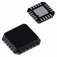
ADF4001 TSSOP R 1 SET CP 2 ADF4001 CPGND 3 AGND 4 TOP VIEW (Not to Scale REF 8 IN TSSOP LFCSP Pin No. Pin No. Mnemonic 1 19 ...
Page 5
–25 –30 – 100 150 FREQUENCY – MHz TPC 1. Input Sensitivity 3.3 V, 100 –5 –10 –15 –20 –25 –30 ...
Page 6
ADF4001 CIRCUIT DESCRIPTION Reference Input Section The reference input stage is shown in Figure 2. SW1 and SW2 are normally closed switches. SW3 is normally open. When power-down is initiated, SW3 is closed and SW1 and SW2 are opened. This ...
Page 7
ANALOG LOCK DETECT DIGITAL LOCK DETECT MUX R COUNTER OUTPUT N COUNTER OUTPUT SDOUT Figure 6. MUXOUT Circuit Lock Detect MUXOUT can be programmed for two types of lock detect: digital lock detect and analog lock detect. Digital lock detect ...
Page 8
ADF4001 ANTI- TEST BACKLASH RESERVED MODE WIDTH BITS DB23 DB22 DB21 DB20 DB19 DB18 DB17 LDP T2 T1 ABP2 X = DON’T CARE ABP2 TEST MODE BITS SHOULD BE SET TO 00 FOR ...
Page 9
RESERVED DB23 DB22 DB21 DB20 DB19 DB18 DB17 X G1 N13 N12 N11 N10 X N13 N12 ...
Page 10
ADF4001 CURRENT CURRENT RESERVED SETTING SETTING 2 DB23 DB22 DB21 DB20 DB19 DB18 DB17 DB16 X X PD2 CPI6 CPI5 CPI4 CPI3 X = DON’T CARE TC4 TC3 ...
Page 11
CURRENT CURRENT RESERVED SETTING SETTING 2 DB23 DB22 DB21 DB20 DB19 DB18 DB17 PD2 CPI6 CPI5 CPI4 CPI3 DON’T CARE TC4 ...
Page 12
ADF4001 FUNCTION LATCH With C2, C1 set the on-chip function latch will be pro- grammed. Table V shows the input data format for programming the function latch. Counter Reset DB2 (F1) is the counter reset bit. When ...
Page 13
INITIALIZATION LATCH When C2 the initialization latch is programmed. This is essentially the same as the function latch (programmed when C2 0). However, when the initialization latch is programmed, there is an additional ...
Page 14
ADF4001 COHERENT CLOCK GENERATION When testing A/D converters often advantageous to use a coherent test system, that is, a system that ensures a specific relationship between the A/D converter input signal and the A/D converter sample rate. Thus, ...
Page 15
INTERFACING ® The ADF4001 family has a simple SPI face for writing to the device. SCLK, SDATA, and LE control the data transfer. When LE (latch enable) goes high, the 24 bits that have been clocked into the input register ...
Page 16
ADF4001 16-Lead Thin Shrink Small Outline Package [TSSOP] 0.15 0.05 PIN 1 INDICATOR 12 MAX 1.00 0.90 0.80 SEATING PLANE Revision History Location 10/03—Data Sheet changed from REV REV. A. Changes to SPECIFICATIONS . . . . . ...