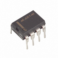
DS1678 Maxim Integrated Products, DS1678 Datasheet - Page 17

DS1678
Manufacturer Part Number
DS1678
Description
IC RECORDER REALTIME EVENT 8-DIP
Manufacturer
Maxim Integrated Products
Type
Time Event Recorderr
Datasheet
1.DS1678S.pdf
(26 pages)
Specifications of DS1678
Memory Size
32B
Time Format
HH:MM:SS (12/24 hr)
Date Format
YY-MM-DD-dd
Interface
I²C, 2-Wire Serial
Voltage - Supply
4.5 V ~ 5.5 V
Operating Temperature
-40°C ~ 85°C
Mounting Type
Through Hole
Package / Case
8-DIP (0.300", 7.62mm)
Lead Free Status / RoHS Status
Contains lead / RoHS non-compliant
Available stocks
Company
Part Number
Manufacturer
Quantity
Price
Part Number:
DS1678
Manufacturer:
DALLAS
Quantity:
20 000
Company:
Part Number:
DS1678S
Manufacturer:
OSRAM
Quantity:
4 193
Company:
Part Number:
DS1678S+
Manufacturer:
NXP
Quantity:
5 799
Part Number:
DS1678S+TR
Manufacturer:
MAXIM/美信
Quantity:
20 000
DS1678
MSB (40h). These will be helpful in recovering all of the data if a rollover occurs. The address pointer
will point to the oldest event in the memory after a rollover. This is the memory location that would be
over written by the next event. Read the data from this point to the end of the memory and the start time
stamp including the 2-byte ETC from last event in order to recover all of the data in the correct order.
GLITCH CONTROL CIRCUIT
The DS1678 has a built-in glitch control circuit to filter noise on the
pin from triggering false events.
INT
A minimum of one internal clock cycle (0.122ms) up to a maximum of two internal clock cycles
(0.245ms) are required to recognize a transition on the input as an event. An event then requires an
additional six to eight internal clock cycles (0.752ms to 0.977ms) to be processed and recorded into
memory. This means that the minimum event occurrence that can be recognized by the DS1678 requires
seven to 10 internal clock cycles (0.854ms to 1.22ms). Failure to ensure this timing will cause the event
to be ignored. Thus, it is recommended that you design with the maximum timing specs.
The
pin has a weak internal pull-down resistor to prevent the pin from floating if the signal
INT
connected to the pin is tri-stated. Without the resistor, the input would float and potentially log phantom
events. With the pull-down resistor, the pin can be transitioned to a low state causing an event to be
recorded if the
pin was being held high by an outside signal that becomes tri-stated.
INT
SECURITY
The DS1678 provides several measures to insure data integrity for the end user. These security measures
are intended to prevent third-party intermediaries from tampering with the data that has been stored in the
event log memory.
As a first security measure, the event log memory is read-only from the perspective of the end user. The
DS1678 can write the data into these memory banks, but the end user cannot write data to individual
registers. This prevents an unscrupulous intermediary from writing false data to the DS1678. The end
user, however, can clear the contents of the event log memory. A new mission can not be started unless
the MEM CLR bit has been set to a 1 to indicate that the memory and registers are cleared.
As a second security measure, changing any value in the memory including the RTC and control registers
will stop event logging and clear the MIP and ME bits. The MEM CLR bit must be set to 1 so that the
memory and registers are cleared before a new event log mission can begin.
POWER CYCLING
When V
falls below 1.25 x V
the device automatically write protects itself, terminates any access in
CC
BAT
progress and resets the device address counter. Inputs to the device via the 2-wire bus will not be
recognized at this time to prevent erroneous data from being written to the device from an out of tolerance
system. When V
falls below V
the device switches into a low-current battery backup mode. Upon
CC
BAT
power-up, the device switches from battery power to V
when V
is greater than V
+ 0.2V and
CC
CC
BAT
recognizes inputs from the system when V
is greater than 1.25 x V
by releasing control of the write
CC
BAT
protection on the 2-wire bus.
2-WIRE SERIAL DATA BUS
The DS1678 supports a bi-directional, 2-wire bus and data transmission protocol. A device that sends
data onto the bus is defined as a transmitter, and a device receiving data as a receiver. The device that
controls the message is called a “master.” The devices that are controlled by the master are “slaves.” The
bus must be controlled by a master device that generates the serial clock (SCL), controls the bus access,
17 of 26


