2007637-5 TE Connectivity, 2007637-5 Datasheet - Page 6
2007637-5
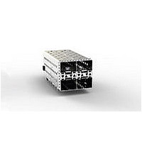
Manufacturer Part Number
2007637-5
Description
CAGE, STACKED, 2X2, SFP+, LIGHT
Manufacturer
TE Connectivity
Datasheet
1.2007637-5.pdf
(10 pages)
Specifications of 2007637-5
Connector Type
Cage
Contact Termination
Press Fit
Connector Mounting
PCB
Contact Plating
Gold
Contact Material
Copper Alloy
Connector Mounting Orientation
PCB
Rohs Compliant
Yes
No. Of Contacts
4
Svhc
No SVHC (15-Dec-2010)
Product Type
Cage
Termination Type
Press-Fit
Configuration
2 x 2
Pcb Mount
Single Sided
Termination Post Length (mm [in])
3.00 [0.118]
Contact Plating, Mating Area, Material
Gold or Gold Flash over Palladium Nickel
Contact Base Material
Copper Alloy
Cage Type
Stacked
Housing Color
Black
Ul Flammability Rating
UL 94V-0
Housing Material
Liquid Crystal Polymer (LCP)
Cage Material
Nickel Silver
Emi Containment
External Springs
Lightpipe
With
Rohs/elv Compliance
RoHS compliant, ELV compliant
Lead Free Solder Processes
Not relevant for lead free process
Rohs/elv Compliance History
Always was RoHS compliant
Application
SFP+
Lightpipe Configuration
Four Per Column
Packaging Method
Tray
Available stocks
Company
Part Number
Manufacturer
Quantity
Price
Company:

Part Number:
2007637-5
Manufacturer:
TYCO
Quantity:
36 560


3.7. Transceiver Modules
3.8. Bezel
3.9. PC Board and Bezel Position
The bezel and pc board must be positioned in relation to each other to avoid interference with the function of
the cage assembly module locking latch and to ensure proper function of the panel ground springs. This
relationship must conform to the dimensions stated in Figure 4.
Note: Not to Scale
6 of 10
CAUTION
CAUTION
Standard
Standard
CONNECTOR AND CAGE ASSY
TYPE
TYPE
A. Thickness
The bezel thickness range shall be 0.8 through 2.6 mm.
B. Cutout
The bezel must provide a cutout that allows proper mounting of the connector and cage assembly. The
cage assembly panel grounding feature must be compressed by the bezel in order to provide an electrical
ground between the connector and cage assembly and bezel for EMI suppression. Care must be used to
avoid interference between adjacent connector and cage assemblies and other components. The
minimum allowable distance between connector and cage assemblies must be considered to ensure
proper assembly. Dimensions for bezel cutout and minimum allowable distance between cutouts are
shown in Figure 4.
!
!
Cutout Centerline to Cutout Centerline
0.30 Maximum
Radius (4 Places)
The mating transceiver module packing size cannot exceed the width of each cage port opening. This includes the part
of the transceiver that is extending outside the cage. Since the port- - to- - port spacing has a 14.25 mm centerline, the
widest transceiver width extending outside of the cage should be less than 14 mm. This will prevent any possible
interference when transceivers are inserted in adjacent ports.
It is strongly recommended that this bezel configuration NOT be used in PCI applications. The following requirements
were intended to be used in the communications industry only.
CONFIGURATION
CONFIGURATION
2¢1
2¢2
2¢4
2¢6
(Min)
B
A
Recommended Bezel Cutout (Minimum Pitch) and
15.45
29.7
58.2
86.7
A
A
Y
Y
PC Board
PC Board and Bezel Position
Bezel Thickness: 0.8- - 2.6 mm
SPRING FINGERS
16.25
C
59.5
31
88
0.00 +0.1 (Bottom of
Cutout in Bezel to
Top of PC Board)
Figure 4
B (Min)
D (Ref)
GASKET
DIMENSION (+0.1)
34.25
62.75
91.25
19.5
26
26
26
26
C
C
Cutout in Bezel
PC Board
3.50 +0.30 (Distance Between Back
of Bezel and Front of PC Board)
SPRING FINGERS
Section Y- - Y
26
26
26
26
D (Ref)
114- 13219
GASKET
26
26
26
26
Rev B
Related parts for 2007637-5
Image
Part Number
Description
Manufacturer
Datasheet
Request
R


Part Number:
Description:
I/O CONNECTOR, RECEPTACLE, 200POS, SMD
Manufacturer:
Molex Inc
Datasheet:

Part Number:
Description:
I/O Connectors Stacked SFP 2x5 Asse 2x5 Assembly Medium
Manufacturer:
Molex Inc

Part Number:
Description:
I/O Connectors Stacked SFP 2x5 Med P 2x5 Med Assy W/ LP
Manufacturer:
Molex Inc
Part Number:
Description:
I/O Connectors Stacked SFP 2x5 Asse ssembly w Lightpipe
Manufacturer:
Molex Inc

Part Number:
Description:
High Speed / Modular Connectors 30P HEADER ASSY
Manufacturer:
TE Connectivity
Datasheet:

Part Number:
Description:
High Speed / Modular Connectors REC 6X005P R/A LT B-PLANE HS3
Manufacturer:
TE Connectivity
Datasheet:

Part Number:
Description:
High Speed / Modular Connectors 2MM HM RCPT 50P R/A AU
Manufacturer:
TE Connectivity
Datasheet:

Part Number:
Description:
High Speed / Modular Connectors 2MM HM RCPT 50P R/A AU
Manufacturer:
TE Connectivity
Datasheet:


Part Number:
Description:
Manufacturer:
TE Connectivity
Datasheet:


Part Number:
Description:
Manufacturer:
TE Connectivity
Datasheet:

Part Number:
Description:
Manufacturer:
TE Connectivity
Datasheet:

Part Number:
Description:
Manufacturer:
TE Connectivity
Datasheet: