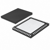
LTC2754AIUKG-16#TRPBF Linear Technology, LTC2754AIUKG-16#TRPBF Datasheet - Page 15

LTC2754AIUKG-16#TRPBF
Manufacturer Part Number
LTC2754AIUKG-16#TRPBF
Description
IC DAC 16BIT QUAD IOUT 52-QFN
Manufacturer
Linear Technology
Datasheet
1.LTC2754IUKG-12PBF.pdf
(28 pages)
Specifications of LTC2754AIUKG-16#TRPBF
Settling Time
2µs
Number Of Bits
16
Data Interface
Serial, SPI™
Number Of Converters
4
Voltage Supply Source
Single Supply
Operating Temperature
-40°C ~ 85°C
Mounting Type
Surface Mount
Package / Case
52-QFN
Lead Free Status / RoHS Status
Lead free / RoHS Compliant
Power Dissipation (max)
-
Available stocks
Company
Part Number
Manufacturer
Quantity
Price
OPERATION
Readback in M-Span Confi guration
If the part is in M-Span confi guration and a DAC Span
register is specifi ed for readback, then the data shifted out
of SRO will refl ect the actual active span. The hardware-
confi gured output range is therefore software detectable
and available for use in programming.
Examples
1. Using a 24-bit instruction, load DAC A with the unipolar
range of 0V to 10V, output at zero volts and all other DACs
with the bipolar range of ±10V, outputs at zero volts. Note
all DAC outputs should change at the same time.
a) CS/LD↓
b) CS/LD↑
±10V.
c) CS/LD↓
d) CS/LD↑
e) CS/LD↓
f) CS/LD↑
g) CS/LD↓
h) CS/LD↑
i) CS/LD↓
j) CS/LD↑
k) Alternatively steps i and j could be replaced with
Clock SDI = 0010 1111 0000 0000 0000 0011
Input register- Range of all DACs set to bipolar
Clock SDI = 0010 0000 0000 0000 0000 0001
Input register- Range of DAC A set to unipolar 0V
to 10V.
Clock SDI = 0011 1111 1000 0000 0000 0000
Input register- Code of all DACs set to midscale.
Clock SDI = 0011 0000 0000 0000 0000 0000
Input register- Code of DAC A set to zero code.
Clock SDI = 0100 1111 XXXX XXXX XXXX XXXX
Update all DACs for both Code and Range.
LDAC
.
2. Using a 32-bit load sequence, load DAC C with bipolar
±2.5V and its output at zero volts. Use readback to check
Input register contents before updating the DAC output
(i.e., before copying Input register contents into DAC
register).
a) CS/LD↓ (Note that after power-on, the code in
b) CS/LD↑
c) CS/LD↓
d) CS/LD↑
e) CS/LD↓
f) CS/LD↓
g) CS/LD↑
h) Alternatively steps f and g could be replaced with
Input register is zero)
Clock SDI = 0000 0000 0011 0100 1000 0000
0000 0000
Input register- Code of DAC C set to midscale
setting.
Clock SDI = 0000 0000 0010 0100 0000 0000
0000 0100
Data out on SRO = 1000 0000 0000 0000 Verifi es
that Input register- Code DAC C is at midscale
setting.
Input register- Range of DAC C set to Bipolar
±2.5V range.
Clock SDI = 0000 0000 1010 0100 xxxx xxxx
xxxx xxxx
Data Out on SRO = 0000 0000 0000 0100
Verifi es that Input register- range of DAC C set to
Bipolar ±2.5V Range.
CS/LD↑
Clock SDI = 0000 0000 0100 0100 xxxx xxxx
xxxx xxxx
Update DAC C for both Code and Range
LDAC
.
LTC2754
15
2754f


