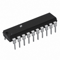
DAC1007LCN National Semiconductor, DAC1007LCN Datasheet - Page 18

DAC1007LCN
Manufacturer Part Number
DAC1007LCN
Description
IC DAC 10BIT MPU DBL BUFF 20-DIP
Manufacturer
National Semiconductor
Series
MICRO-DAC™r
Datasheet
1.DAC1006LCN.pdf
(24 pages)
Specifications of DAC1007LCN
Settling Time
500ns
Number Of Bits
9
Number Of Converters
1
Voltage Supply Source
Single Supply
Power Dissipation (max)
500mW
Operating Temperature
0°C ~ 70°C
Mounting Type
Through Hole
Package / Case
*
Lead Free Status / RoHS Status
Contains lead / RoHS non-compliant
Data Interface
-
Other names
*DAC1007LCN
Available stocks
Company
Part Number
Manufacturer
Quantity
Price
Part Number:
DAC1007LCN
Manufacturer:
BB
Quantity:
20 000
www.national.com
DAC1006/1007/1008 — Simple Hookup for a “Quick Look”
Three operating modes are possible: flow through, single
buffered, or double buffered. The timing diagrams for these
are shown below:
6.3.1 Single Buffered
6.3.2 Double Buffered
6.4 Stand Alone Operation
For applications for a DAC which are not under µP control
(stand alone) there are two basic operating modes, single
buffered and double buffered. The timing diagrams for these
are shown below:
DAC1006/1007/1008 (20-Pin Parts)
DAC1006/1007/1008 (20-Pin Parts)
FIGURE 17. Input Connections and Logic for DAC1006/1007/1008 with 16-Bit Data Bus
DS005688-51
DS005688-52
18
6.4.1 Single Buffered
6.4.2 Double Buffered
Note 12: For a connection diagram of this operating mode use Figure 16 for
the Logic and Figure 17 for the Data Input connections.
7.0 MICROPROCESSOR INTERFACE
The logic functions of the DAC1006 family have been ori-
ented towards an ease of interface with all popular µPs. The
following sections discuss in detail a few useful interface
schemes.
7.1 DAC1001/1/2 to INS8080A Interface
Figure 18 illustrates the simplicity of interfacing the
DAC1006 to an INS8080A based microprocessor system.
The circuit will perform an automatic transfer of the 10 bits of
output data from the CPU to the DAC register as outlined in
Section 6.2.1, “Controlling Data Transfer for an 8-Bit Data
Bus.”
Since a double byte write is necessary to control the DAC
with the INS8080A, a possible instruction to achieve this is a
PUSH of a register pair onto a “stack” in memory. The 16-bit
register pair word will contain the 10 bits of the eventual DAC
input data in the proper sequence to conform to both the re-
quirements of the DAC (with regard to left justified data) and
DAC1006/1007/1008 (20-Pin Parts) (Note 12)
DAC1006/1007/1008 (20-Pin Parts)
(Continued)
DS005688-21
DS005688-54
DS005688-53


