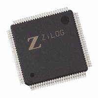
EZ80L92AZ050SG Zilog, EZ80L92AZ050SG Datasheet - Page 51

EZ80L92AZ050SG
Manufacturer Part Number
EZ80L92AZ050SG
Description
IC WEBSERVER 50MHZ 100LQFP
Manufacturer
Zilog
Datasheet
1.EZ80L92AZ020SG.pdf
(231 pages)
Specifications of EZ80L92AZ050SG
Processor Type
eZ80
Features
High Speed, Single-Cycle Instruction-Fetch
Speed
50MHz
Voltage
3.3V
Mounting Type
Surface Mount
Package / Case
100-LQFP
Processor Series
EZ80L92x
Core
eZ80
Data Bus Width
8 bit
Program Memory Size
64 KB
Interface Type
I2C, SPI, UART
Maximum Clock Frequency
50 MHz
Number Of Programmable I/os
24
Number Of Timers
6
Operating Supply Voltage
3 V to 3.6 V
Maximum Operating Temperature
+ 70 C
Mounting Style
SMD/SMT
Development Tools By Supplier
eZ80L920210ZCO
Minimum Operating Temperature
0 C
Lead Free Status / RoHS Status
Lead free / RoHS Compliant
Other names
269-3878
EZ80L92AZ050SG
EZ80L92AZ050SG
Available stocks
Company
Part Number
Manufacturer
Quantity
Price
Company:
Part Number:
EZ80L92AZ050SG
Manufacturer:
Everlight
Quantity:
12 000
- Current page: 51 of 231
- Download datasheet (3Mb)
Table 12. Vectored Interrupt Operation
PS013014-0107
Memory
Mode
Z80 Mode
ADL
Bit
{MBASE[7:0], I[7:0], 1Eh} and {MBASE, I[7:0], 1Fh}. The least significant byte is
stored at the lower address.
When any one or more of the interrupt requests (IRQs) become active, an interrupt request
is generated by the interrupt controller and sent to the CPU. The corresponding 8-bit
interrupt vector for the highest priority interrupt is placed on the 8-bit interrupt vector bus,
IVECT[7:0]. The interrupt vector bus is internal to the eZ80L92 and is therefore not
visible externally. The response time of the eZ80 CPU to an interrupt request is a
function of the current instruction being executed as well as the number of WAIT states
being asserted.
The interrupt vector, {I[7:0], IVECT[7:0]}, is visible on the address bus, ADDR[15:0],
when the interrupt service routine begins. The response of the eZ80 CPU to a vectored
interrupt on the eZ80L92 is explained in
active until the Interrupt Service Routine (ISR) starts. We recommend you to change the
Interrupt Page Address Register (I) value from its default value of 00h as this address can
create conflicts between the non-maskable interrupt vector, the RST instruction addresses,
and the maskable interrupt vectors.
0
MADL
Bit
0
Operation
Read the LSB of the interrupt vector placed on the internal vectored
interrupt bus, IVECT [7:0], by the interrupting peripheral.
•
•
•
•
•
•
•
•
•
IEF1 ← 0
IEF2 ← 0
The starting Program Counter is effectively {MBASE, PC[15:0]}.
Push the 2-byte return address PC[15:0] on the ({MBASE,SPS}) stack.
The ADL mode bit remains cleared to 0.
The interrupt vector address is located at { MBASE, I[7:0], IVECT[7:0] }.
PC[15:0] ← ( { MBASE, I[7:0], IVECT[7:0] } ).
The ending Program Counter is effectively {MBASE, PC[15:0]}
The interrupt service routine must end with RETI.
Table
12. Interrupt sources are required to be
Product Specification
Interrupt Controller
eZ80L92 MCU
45
Related parts for EZ80L92AZ050SG
Image
Part Number
Description
Manufacturer
Datasheet
Request
R

Part Number:
Description:
Communication Controllers, ZILOG INTELLIGENT PERIPHERAL CONTROLLER (ZIP)
Manufacturer:
Zilog, Inc.
Datasheet:

Part Number:
Description:
KIT DEV FOR Z8 ENCORE 16K TO 64K
Manufacturer:
Zilog
Datasheet:

Part Number:
Description:
KIT DEV Z8 ENCORE XP 28-PIN
Manufacturer:
Zilog
Datasheet:

Part Number:
Description:
DEV KIT FOR Z8 ENCORE 8K/4K
Manufacturer:
Zilog
Datasheet:

Part Number:
Description:
KIT DEV Z8 ENCORE XP 28-PIN
Manufacturer:
Zilog
Datasheet:

Part Number:
Description:
DEV KIT FOR Z8 ENCORE 4K TO 8K
Manufacturer:
Zilog
Datasheet:

Part Number:
Description:
CMOS Z8 microcontroller. ROM 16 Kbytes, RAM 256 bytes, speed 16 MHz, 32 lines I/O, 3.0V to 5.5V
Manufacturer:
Zilog, Inc.
Datasheet:

Part Number:
Description:
Low-cost microcontroller. 512 bytes ROM, 61 bytes RAM, 8 MHz
Manufacturer:
Zilog, Inc.
Datasheet:

Part Number:
Description:
Z8 4K OTP Microcontroller
Manufacturer:
Zilog, Inc.
Datasheet:

Part Number:
Description:
CMOS SUPER8 ROMLESS MCU
Manufacturer:
Zilog, Inc.
Datasheet:

Part Number:
Description:
SL1866 CMOSZ8 OTP Microcontroller
Manufacturer:
Zilog, Inc.
Datasheet:

Part Number:
Description:
SL1866 CMOSZ8 OTP Microcontroller
Manufacturer:
Zilog, Inc.
Datasheet:

Part Number:
Description:
OTP (KB) = 1, RAM = 125, Speed = 12, I/O = 14, 8-bit Timers = 2, Comm Interfaces Other Features = Por, LV Protect, Voltage = 4.5-5.5V
Manufacturer:
Zilog, Inc.
Datasheet:

Part Number:
Description:
Manufacturer:
Zilog, Inc.
Datasheet:


