PCF8584P,112 NXP Semiconductors, PCF8584P,112 Datasheet - Page 24
PCF8584P,112
Manufacturer Part Number
PCF8584P,112
Description
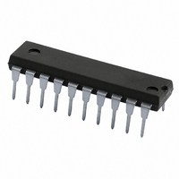
IC CTRL PARALLEL/I2C BUS 20-DIP
Manufacturer
NXP Semiconductors
Datasheet
1.PCF8584P112.pdf
(40 pages)
Specifications of PCF8584P,112
Package / Case
20-DIP (0.300", 7.62mm)
Controller Type
Parallel Bus to I²C Bus Controller
Interface
Parallel
Voltage - Supply
4.5 V ~ 5.5 V
Current - Supply
1.5mA
Operating Temperature
-40°C ~ 85°C
Mounting Type
Through Hole
Maximum Operating Temperature
+ 85 C
Minimum Operating Temperature
- 40 C
Mounting Style
Through Hole
Operating Supply Voltage
4.5 V to 5.5 V
Lead Free Status / RoHS Status
Lead free / RoHS Compliant
Lead Free Status / RoHS Status
Lead free / RoHS Compliant, Lead free / RoHS Compliant
Other names
568-3532-5
935069300112
PCF8584PN
935069300112
PCF8584PN


Philips Semiconductors
12 I
All the timing limits are valid within the operating supply voltage and ambient temperature range; V
T
13 PARALLEL INTERFACE TIMING
All the timing limits are valid within the operating supply voltage and ambient temperature range: V
T
(connected to V
1997 Oct 21
f
t
t
t
t
t
t
t
t
t
t
t
t
t
t
t
t
t
t
t
t
t
t
t
t
t
t
t
t
t
amb
SCL
SW
BUF
SU;STA
HD;STA
LOW
HIGH
r
f
SU;DAT
HD;DAT
VD;DAT
SU;STO
amb
r
f
CLK
CLRL
CLWL
RHCH
WHCH
AVWL
AVRL
WHAI
RHAI
WLWH
RLRH
DVWH
RLDV
WHDI
RHDF
SYMBOL
SYMBOL
I
2
C-bus controller
2
= 40 to +85 C; and refer to V
= 40 to +85 C; and refer to V
C-BUS TIMING SPECIFICATIONS
SCL clock frequency
tolerable spike width on bus
bus free time
START condition set-up time
START condition hold time
SCL LOW time
SCL HIGH time
SCL and SDA rise time
SCL and SDA fall time
data set-up time
data hold time
SCL LOW to data out valid
STOP condition set-up time
clock rise time
clock fall time
input clock period
(50% 5% duty factor)
CS set-up to RD LOW
CS set-up to WR LOW
CS hold from RD HIGH
CS hold from WR HIGH
A0 set-up to WR LOW
A0 set-up to RD LOW
A0 hold from WR HIGH
A0 hold from RD HIGH
WR pulse width
RD pulse width
data set-up before WR HIGH
data valid after RD LOW
data hold after WR HIGH
data bus floating after RD
HIGH
DD
) for open-drain and high-impedance outputs, where applicable (for measurement purposes only).
PARAMETER
PARAMETER
IL
IL
and V
and V
IH
IH
with an input voltage of V
with an input voltage of V
see Fig.14
see Fig.14
see Fig.14
see Fig.16 and note 1 20
see Fig.15 and note 1 20
see Fig.16
see Fig.15
see Fig.15
see Fig.16
see Fig.15
see Fig.16
see Fig.15
see Fig.16
see Fig.15
see Fig.16
see Fig.15
see Fig.16
CONDITIONS
24
4.7
4.7
4.0
4.7
4.0
250
0
4.0
83
0
0
10
10
20
10
230
230
150
20
SS
SS
MIN.
MIN.
to V
to V
DD.
DD
. C
160
L
= 100 pF; R
TYP.
TYP.
L
100
100
1.0
0.3
3.4
6
6
333
1000
1000
150
Product specification
180
DD
DD
= 1.5 k
MAX.
MAX.
= 5 V 10%;
= 5 V 10%;
PCF8584
kHz
ns
ns
ns
ns
ns
ns
ns
ns
ns
ns
ns
ns
ns
ns
ns
ns
ns
ns
ns
ns
UNIT
UNIT
s
s
s
s
s
s
s
s
s
Related parts for PCF8584P,112
Image
Part Number
Description
Manufacturer
Datasheet
Request
R

Part Number:
Description:
Manufacturer:
NXP Semiconductors
Datasheet:

Part Number:
Description:
Manufacturer:
NXP Semiconductors
Datasheet:
Part Number:
Description:
NXP Semiconductors designed the LPC2420/2460 microcontroller around a 16-bit/32-bitARM7TDMI-S CPU core with real-time debug interfaces that include both JTAG andembedded trace
Manufacturer:
NXP Semiconductors
Datasheet:

Part Number:
Description:
NXP Semiconductors designed the LPC2458 microcontroller around a 16-bit/32-bitARM7TDMI-S CPU core with real-time debug interfaces that include both JTAG andembedded trace
Manufacturer:
NXP Semiconductors
Datasheet:
Part Number:
Description:
NXP Semiconductors designed the LPC2468 microcontroller around a 16-bit/32-bitARM7TDMI-S CPU core with real-time debug interfaces that include both JTAG andembedded trace
Manufacturer:
NXP Semiconductors
Datasheet:
Part Number:
Description:
NXP Semiconductors designed the LPC2470 microcontroller, powered by theARM7TDMI-S core, to be a highly integrated microcontroller for a wide range ofapplications that require advanced communications and high quality graphic displays
Manufacturer:
NXP Semiconductors
Datasheet:
Part Number:
Description:
NXP Semiconductors designed the LPC2478 microcontroller, powered by theARM7TDMI-S core, to be a highly integrated microcontroller for a wide range ofapplications that require advanced communications and high quality graphic displays
Manufacturer:
NXP Semiconductors
Datasheet:
Part Number:
Description:
The Philips Semiconductors XA (eXtended Architecture) family of 16-bit single-chip microcontrollers is powerful enough to easily handle the requirements of high performance embedded applications, yet inexpensive enough to compete in the market for hi
Manufacturer:
NXP Semiconductors
Datasheet:
Part Number:
Description:
The XA-S3 device is a member of Philips Semiconductors? XA(eXtended Architecture) family of high performance 16-bitsingle-chip microcontrollers
Manufacturer:
NXP Semiconductors
Datasheet:

Part Number:
Description:
The NXP BlueStreak LH75401/LH75411 family consists of two low-cost 16/32-bit System-on-Chip (SoC) devices
Manufacturer:
NXP Semiconductors
Datasheet:
Part Number:
Description:
The NXP LPC3130/3131 combine an 180 MHz ARM926EJ-S CPU core, high-speed USB2
Manufacturer:
NXP Semiconductors
Datasheet:
Part Number:
Description:
The NXP LPC3141 combine a 270 MHz ARM926EJ-S CPU core, High-speed USB 2
Manufacturer:
NXP Semiconductors
Part Number:
Description:
The NXP LPC3143 combine a 270 MHz ARM926EJ-S CPU core, High-speed USB 2
Manufacturer:
NXP Semiconductors

Part Number:
Description:
The NXP LPC3152 combines an 180 MHz ARM926EJ-S CPU core, High-speed USB 2
Manufacturer:
NXP Semiconductors