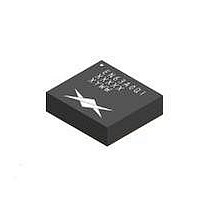
EN63A0QI-E Enpirion, EN63A0QI-E Datasheet - Page 19

EN63A0QI-E
Manufacturer Part Number
EN63A0QI-E
Description
Power Management Development Tools EN63A0QI Eval Board 12A Hi Eff Buck Con
Manufacturer
Enpirion
Type
DC/DC Switching Converters, Regulators & Controllersr
Specifications of EN63A0QI-E
Maximum Operating Temperature
+ 85 C
Minimum Operating Temperature
- 40 C
Operating Supply Voltage
2.375 V to 6.6 V
Output Current
12 A
Product
Power Management Development Tools
Lead Free Status / Rohs Status
Lead free / RoHS Compliant
For Use With/related Products
EN63A0QI
Thermal Considerations
Thermal considerations are important power supply
design facts that cannot be avoided in the real
world. Whenever there are power losses in a
system, the heat that is generated by the power
dissipation needs to be accounted for. The Enpirion
PowerSoC helps alleviate some of those concerns.
The Enpirion EN63A0QI DC-DC converter is
packaged in an 10x11x3mm 76-pin QFN package.
The QFN package is constructed with copper lead
frames that have exposed thermal pads. The
exposed thermal pad on the package should be
soldered directly on to a copper ground pad on the
printed circuit board (PCB) to act as a heat sink.
The recommended maximum junction temperature
for continuous operation is 125° C. Continuous
operation above 125° C may reduce long-term
reliability. The device has a thermal overload
protection circuit designed to turn off the device at
an approximate junction temperature value of
150° C.
The following example and calculations illustrate
the thermal performance of the EN63A0QI.
Example:
V
V
I
First calculate the output power.
P
Next, determine the input power based on the
efficiency (η) shown in Figure 8.
For V
η = P
©Enpirion 2012 all rights reserved, E&OE
OUT
07077
IN
OUT
OUT
= 5V
= 12A
100
= 1.8V x 12A = 21.6W
= 1.8V
90
80
70
60
50
40
30
20
10
OUT
IN
0
= 5V, V
0
Figure 8: Efficiency vs. Output Current
/ P
1
IN
Efficiency vs. Output Current
= 87% = 0.85
2
OUT
OUTPUT CURRENT (A)
3
VOUT = 1.8V
= 1.8V at 12A, η ≈ 85%
4
5
6
7
8
CONDITIONS
V
T
A
IN
~85%
= 85 C
= 5.0V
9
10 11 12
Enpirion Confidential
May 9, 2012
P
P
The power dissipation (P
system and can be calculated by subtracting the
output power from the input power.
P
With the power dissipation known, the temperature
rise in the device may be estimated based on the
theta JA value (θ
how much the temperature will rise in the device for
every watt of power dissipation. The EN63A0QI has
a θ
Determine the change in temperature (∆T) based
on P
∆T = P
∆T ≈ 3.81W x 14° C/W = 53.36° C ≈ 53° C
The junction temperature (T
approximately the ambient temperature (T
the change in temperature. We assume the initial
ambient temperature to be 25° C.
T
T
The maximum operating junction temperature
(T
operate at a higher ambient temperature. The
maximum ambient temperature (T
be calculated.
T
The maximum ambient temperature the device can
reach is 72° C given the input and output conditions.
Note that the efficiency used in this example is at
85° C ambient temperature and is a worst case
condition. Refer to the de-rating curves in the
Typical Performance Curves section.
J
J
AMAX
IN
IN
D
JMAX
= T
≈ 25° C + 53° C ≈ 78° C
= P
≈ 25.41W – 21.6 ≈ 3.81W
JA
= P
≈ 21.6W / 0.85 ≈ 25.41W
D
value of 14 ºC/W without airflow.
) of the device is 125° C, so the device can
A
= T
and θ
≈ 125° C – 53° C ≈ 72° C
IN
D
OUT
+ ∆T
– P
x θ
JMAX
/ η
JA
JA
OUT
.
– P
D
JA
x θ
). The θ
JA
www.enpirion.com, Page 19
D
) is the power loss in the
JA
parameter estimates
J
) of the device is
AMAX
EN63A0QI
) allowed can
A
) plus
Rev: C


