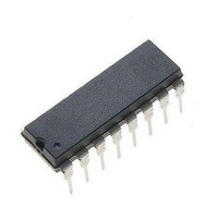
MC44603P ON Semiconductor, MC44603P Datasheet

MC44603P
Specifications of MC44603P
Available stocks
Related parts for MC44603P
MC44603P Summary of contents
Page 1
MC44603A Enhanced Mixed Frequency Mode GreenLinet PWM Controller: Fixed Frequency, Variable Frequency, Standby Mode The MC44603A is an enhanced high performance controller that is specifically designed for off−line and dc−to−dc converter applications. This device has the unique ability of automatically ...
Page 2
... Low dV/dT for Low EMI Radiations *For additional information on our Pb−Free strategy and soldering details, please download the ON Semiconductor Soldering and Mounting Techniques Reference Manual, SOLDERRM/D. http://onsemi.com 2 ...
Page 3
MAXIMUM RATINGS Rating Total Power Supply and Zener Current Supply Voltage with Respect to Ground (Pin 4) Output Current (Note 1) Source Sink Output Energy (Capacitive Load per Cycle Soft−Start Inputs F Stby ...
Page 4
ELECTRICAL CHARACTERISTICS 25°C, for min/max values T = −25° to +85°C (Note 3), unless otherwise noted.) A Characteristic OUTPUT SECTION Output Voltage (Note 4) Low State (I = 100 mA) Sink Low State (I = 500 mA) Sink High State ...
Page 5
ELECTRICAL CHARACTERISTICS (continued) (V 25°C, for min/max values T = −25° to +85°C (Note 3), unless otherwise noted.) A Characteristic OSCILLATOR AND SYNCHRONIZATION SECTION Oscillator Voltage Swing (Peak−to−Peak) Ratio Charge Current/Reference Current T = 0° to +70° 2.0 ...
Page 6
ELECTRICAL CHARACTERISTICS (continued) (V 25°C, for min/max values T = −25° to +85°C (Note 3), unless otherwise noted.) A Characteristic SOFT−START SECTION (Note 10) Duty Cycle ( kW) soft−start Duty Cycle (V = 0.1 V) soft−start (Pin 11) ...
Page 7
Negative R Q Active S Clamp Demag Detect 3.7 V Sync Input V 9 ref + 0.4 I 0.7 V ref 1 3.6 V ...
Page 8
C = 100 500 1000 2200 100 Oscillator Frequency (Hz) OSC Figure 2. Timing Resistor versus Oscillator Frequency ...
Page 9
T , AMBIENT TEMPERATURE (°C) A Figure 8. Oscillator Discharge Current versus Temperature 2.0 Sink Saturation (Load 1.6 CC 1.2 0 ...
Page 10
T , AMBIENT TEMPERATURE (°C) A Figure 14. Current Sense Gain versus Temperature 140 120 100 80 -50 - AMBIENT TEMPERATURE (°C) A Figure 16. ...
Page 11
T , AMBIENT TEMPERATURE (°C) A Figure 20. Startup Threshold Voltage versus Temperature 8.0 7.8 7.6 7.4 7.2 7.0 6.8 -50 - AMBIENT TEMPERATURE (°C) A ...
Page 12
T , AMBIENT TEMPERATURE (°C) A Figure 26. Standby Reference Current versus Temperature PIN FUNCTION DESCRIPTION Pin Name 1 V This pin is the positive supply of ...
Page 13
No-Take Over Startup Restart prot V stup-th V disable1 V disable2 V ref UVLO1 V Pin 11 (Soft-Start) V OVP Out Output Ï Ï Ï Ï Ï Ï Ï Ï Ï Ï Ï Ï Ï Ï ...
Page 14
stup-th V disable1 V disable2 V ref UVLO1 V Pin 11 (Soft-Start) Output (Pin 0.3 mA Figure 30. Switching Off Behavior Stby V Demag Out V OSC ...
Page 15
V ref V + 1.6 V CSS V 3 low 1 OSC Output (Pin 3) Error Amplifier A fully compensated Error Amplifier with access to the inverting input and output is provided. It features ...
Page 16
Thus, the error signal controls the peak inductor current on a cycle−by−cycle basis. The Current Sense Comparator PWM Latch ensures that only a single pulse appears at the Source Output during the appropriate oscillator cycle. The inductor current ...
Page 17
Consequently charge T charge DV/I discharge T discharge where the oscillator charge time charge DV is the oscillator peak−to−peak value I is the oscillator charge current charge and T ...
Page 18
ICL + AC Line R startup V CC MC44603A Figure 40. Power Losses in a Classical Flyback Structure In a classical flyback (as depicted in Figure 40), the standby losses mainly consist of the energy waste due ...
Page 19
In order to prevent undesired mode switching when power is close to the threshold value, a hysteresis that is proportional incorporated creating a second R P Stby V threshold level that is equal to [2 ...
Page 20
V out V O Nominal New Startup Sequence Initiated disable2 Figure 46. Foldback Characteristic NOTE: Foldback is disabled by connecting Pin Overvoltage Protection The overvoltage arrangement consists of a comparator that compares the Pin ...
Page 21
Undervoltage Lockout Section R F Stby V ref enable startup Voltage and Current Startup disable2 7 UVLO1 UVLO1 (to Soft-Start) V disable1 9.0 V Figure 48. V ...
Page 22
VAC to 270 VAC RFI Filter R1 1.0/5 ... C7 1.0 nF/1000 V D1 ... D4 1N4007 R2 68 k/2.0 W Sync C16 C8 2.2 nF 100 1 C15 C10 ...
Page 23
W Input Power Fly−Back Converter 185 V − 270 V Mains Range MC44603AP & MTP6N60E Tests Line Regulation 150 V 130 V 114 V 7.0 V Load Regulation 150 V Cross Regulation 150 V Efficiency Standby Mode P input ...
Page 24
... Opportunity/Affirmative Action Employer. This literature is subject to all applicable copyright laws and is not for resale in any manner. PUBLICATION ORDERING INFORMATION LITERATURE FULFILLMENT: Literature Distribution Center for ON Semiconductor P.O. Box 5163, Denver, Colorado 80217 USA Phone: 303−675−2175 or 800−344−3860 Toll Free USA/Canada Fax: 303− ...


