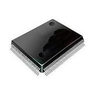
ST92F120V1Q7 STMicroelectronics, ST92F120V1Q7 Datasheet - Page 134

ST92F120V1Q7
Manufacturer Part Number
ST92F120V1Q7
Description
Microcontrollers (MCU) Flash 128K SPI/I2C
Manufacturer
STMicroelectronics
Datasheet
1.ST92F120V9Q7.pdf
(325 pages)
Specifications of ST92F120V1Q7
Data Bus Width
8 bit, 16 bit
Program Memory Type
Flash
Program Memory Size
128 KB
Data Ram Size
4 KB
Interface Type
I2C, SPI
Maximum Clock Frequency
24 MHz
Number Of Programmable I/os
77
Number Of Timers
5
Maximum Operating Temperature
+ 105 C
Mounting Style
SMD/SMT
Package / Case
PQFP-100
Minimum Operating Temperature
- 40 C
On-chip Adc
8 bit, 16 Channel
Lead Free Status / Rohs Status
No
Available stocks
Company
Part Number
Manufacturer
Quantity
Price
Company:
Part Number:
ST92F120V1Q7
Manufacturer:
ST
Quantity:
6 765
Part Number:
ST92F120V1Q7
Manufacturer:
ST
Quantity:
20 000
Part Number:
ST92F120V1Q7C
Manufacturer:
ST
Quantity:
20 000
Company:
Part Number:
ST92F120V1Q7DTR
Manufacturer:
MAXIM
Quantity:
2 854
- Current page: 134 of 325
- Download datasheet (3Mb)
STANDARD TIMER (STIM)
STANDARD TIMER (Cont’d)
10.2.5 Register Description
COUNTER HIGH BYTE REGISTER (STH)
R240 - Read/Write
Register Page: 11
Reset value: 1111 1111 (FFh)
Bits 7:0 = ST.[15:8]: Counter High-Byte.
COUNTER LOW BYTE REGISTER (STL)
R241 - Read/Write
Register Page: 11
Reset value: 1111 1111 (FFh)
Bits 7:0 = ST.[7:0]: Counter Low Byte.
Writing to the STH and STL registers allows the
user to enter the Standard Timer constant, while
reading it provides the counter’s current value.
Thus it is possible to read the counter on-the-fly.
STANDARD TIMER PRESCALER REGISTER
(STP)
R242 - Read/Write
Register Page: 11
Reset value: 1111 1111 (FFh)
Bits 7:0 = STP.[7:0]: Prescaler.
The Prescaler value for the Standard Timer is pro-
grammed into this register. When reading the STP
register, the returned value corresponds to the
programmed data instead of the current data.
00h: No prescaler
01h: Divide by 2
FFh: Divide by 256
134/324
9
STP.7 STP.6 STP.5 STP.4 STP.3 STP.2 STP.1 STP.0
ST.15 ST.14 ST.13 ST.12 ST.11 ST.10
ST.7
7
7
7
ST.6
ST.5
ST.4
ST.3
ST.2
ST.9
ST.1
ST.8
ST.0
0
0
0
STANDARD
(STC)
R243 - Read/Write
Register Page: 11
Reset value: 0001 0100 (14h)
Bit 7 = ST-SP: Start-Stop Bit.
This bit is set and cleared by software.
0: Stop counting
1: Start counting
Bit 6 = S-C: Single-Continuous Mode Select.
This bit is set and cleared by software.
0: Continuous Mode
1: Single Mode
Bits 5:4 = INMD[1:2]: Input Mode Selection.
These bits select the Input functions as shown in
Section 0.1.2.2, when enabled by INEN.
Bit 3 = INEN: Input Enable.
This bit is set and cleared by software. If neither
the STIN pin nor the CLOCK2 line are present,
INEN must be 0.
0: Input section disabled
1: Input section enabled
Bit 2 = INTS: Interrupt Selection.
0: Standard Timer interrupt enabled
1: Standard Timer interrupt is disabled and the ex-
Bits 1:0 = OUTMD[1:2]: Output Mode Selection.
These bits select the output functions as described
in Section 0.1.2.4.
ST
INMD1 INMD2 Mode
0
0
1
1
OUTMD1 OUTMD2 Mode
0
0
1
ternal interrupt pin is enabled.
7
-
SP S-C INMD1 INMD2 INEN INTS OUTMD1 OUTMD2
0
1
0
1
0
1
x
TIMER
Event Counter mode
Gated input mode
Triggerable mode
Retriggerable mode
No output mode
Square wave output mode
PWM output mode
CONTROL
REGISTER
0
Related parts for ST92F120V1Q7
Image
Part Number
Description
Manufacturer
Datasheet
Request
R

Part Number:
Description:
8/16-bit Flash Mcu Family With Ram, Eeprom And J1850 Blpd
Manufacturer:
STMicroelectronics
Datasheet:

Part Number:
Description:
STMicroelectronics [RIPPLE-CARRY BINARY COUNTER/DIVIDERS]
Manufacturer:
STMicroelectronics
Datasheet:

Part Number:
Description:
STMicroelectronics [LIQUID-CRYSTAL DISPLAY DRIVERS]
Manufacturer:
STMicroelectronics
Datasheet:

Part Number:
Description:
BOARD EVAL FOR MEMS SENSORS
Manufacturer:
STMicroelectronics
Datasheet:

Part Number:
Description:
NPN TRANSISTOR POWER MODULE
Manufacturer:
STMicroelectronics
Datasheet:

Part Number:
Description:
TURBOSWITCH ULTRA-FAST HIGH VOLTAGE DIODE
Manufacturer:
STMicroelectronics
Datasheet:

Part Number:
Description:
Manufacturer:
STMicroelectronics
Datasheet:

Part Number:
Description:
DIODE / SCR MODULE
Manufacturer:
STMicroelectronics
Datasheet:

Part Number:
Description:
DIODE / SCR MODULE
Manufacturer:
STMicroelectronics
Datasheet:

Part Number:
Description:
Search -----> STE16N100
Manufacturer:
STMicroelectronics
Datasheet:

Part Number:
Description:
Search ---> STE53NA50
Manufacturer:
STMicroelectronics
Datasheet:

Part Number:
Description:
NPN Transistor Power Module
Manufacturer:
STMicroelectronics
Datasheet:


