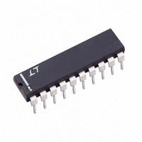
LTC1061ACN Linear Technology, LTC1061ACN Datasheet - Page 6

LTC1061ACN
Manufacturer Part Number
LTC1061ACN
Description
IC FILTER BUILDNG BLK TRPL 20DIP
Manufacturer
Linear Technology
Datasheet
1.LTC1061CNPBF.pdf
(16 pages)
Specifications of LTC1061ACN
Filter Type
Universal Switched Capacitor
Frequency - Cutoff Or Center
35kHz
Number Of Filters
3
Max-order
6th
Voltage - Supply
4.74 V ~ 16 V, ±2.37 V ~ 8 V
Mounting Type
Through Hole
Package / Case
20-DIP (0.300", 7.62mm)
Lead Free Status / RoHS Status
Contains lead / RoHS non-compliant
Available stocks
Company
Part Number
Manufacturer
Quantity
Price
Company:
Part Number:
LTC1061ACN#PBF
Manufacturer:
LT
Quantity:
1 001
f
CLK
LTC1061
PI
T
6
50/100/Hold (Pin 7)
By tying Pin 7 to V
center frequency internally set at 50:1. When Pin 7 is at
mid-supplies, the filter operates with a 100:1 clock-to-
center frequency ratio. Table 1 shows the allowable varia-
tion of the potential at Pin 7 when the 100:1 mode is
sought.
When Pin 7 is shorted to the negative supply pin, the filter
operation is stopped and the bandpass and lowpass
output act as a sample-and-hold circuit holding the last
sample of the input voltage. The hold step is around 2mV
and the droop rate is 150µV/sec.
2
L CLOCK
< 1MHz
Figure 1. The 6th Order LP Butterworth Filter of Figure 5
Operating with a Single 5V Supply
U
1µF
TOTAL POWER SUPPLY
5V
IN
DESCRIPTIO A D
+
(V)
10
15
5
2.49k
2.49k
0.1µF
R1
R3
R2
+
, the filter operates with a clock-to-
10
1
2
3
4
5
6
7
8
9
Table 1
U
LTC1061
VOLTAGE RANGE OF PIN 7
FOR 100:1 OPERATION (V)
U
2.5 ± 0.5
7.5 ±1.5
20
19
18
17
16
15
14
13
12
11
5 ±1
APPLICATIO
R3
R2
1061 F01
V
OUT
R1
R4
R3
R2
C
IN
V
IN
R1
U
Definition of Filter Functions
Refer to LTC1060 data sheet.
Clock Feedthrough
This is defined as the amplitude of the clock frequency
appearing at the output pins of the device, Figure 2. Clock
feedthrough is measured with all three sides of the LTC1061
connected as filters. The clock feedthrough mainly de-
pends on the magnitude of the power supplies and it is
independent from the input clock levels, clock frequency
and modes of operation.
The Table 2 illustrates the typical clock feedthrough num-
bers for various power supplies.
Figure 2. Typical Clock Feedthrogh of the LTC1061 Operating
with ±5V Supplies. Top Trace is the Input Clock Swinging 0V to
5V and Bottom Trace is One of the Lowpass Outputs with Zero or
DC Input Signals.
B = 10mV/DIV
HI TS
A = 2V/DIV
U
POWER SUPPLY (V)
±2.5
±5
±8
Table 2
HORIZONTAL = 10µs/DIV
CLOCK FEEDTHROUGH (V
0.2
0.4
0.8
RMS
1061 F02
)
1061fe


