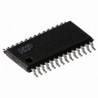
PCA9558PW,118 NXP Semiconductors, PCA9558PW,118 Datasheet - Page 15

PCA9558PW,118
Manufacturer Part Number
PCA9558PW,118
Description
IC I2C SMBUS 8BIT I/O 28TSSOP
Manufacturer
NXP Semiconductors
Datasheet
1.PCA9558PW112.pdf
(27 pages)
Specifications of PCA9558PW,118
Package / Case
28-TSSOP
Applications
PC's, PDA's
Interface
I²C
Voltage - Supply
3 V ~ 3.6 V
Mounting Type
Surface Mount
Logic Family
PCA9558
Number Of Lines (input / Output)
8.0 / 8.0
Propagation Delay Time
21 ns
Operating Supply Voltage
3 V to 3.6 V
Operating Temperature Range
0 C to + 70 C
Input Voltage
5 V
Logic Type
I2C, SMBus
Maximum Clock Frequency
400 KHz
Mounting Style
SMD/SMT
Number Of Input Lines
8.0
Number Of Output Lines
8.0
Output Voltage
5 V
Lead Free Status / RoHS Status
Lead free / RoHS Compliant
Lead Free Status / RoHS Status
Lead free / RoHS Compliant, Lead free / RoHS Compliant
Other names
935269433118
PCA9558PW-T
PCA9558PW-T
PCA9558PW-T
PCA9558PW-T
NXP Semiconductors
8. Application design-in information
PCA9558_4
Product data sheet
Fig 18. Typical application
CPU
OR
C
I
2
C-bus
I
2
C-bus multiplexer
PCA9544A
4-channel
(EEPROM address), and then the Data1 (data byte). A read from the EEPROM would be
a two-step process. The first step would be to do a ‘Write Byte’ with the EEPROM address
in the Data0 register. The second step would be to do a ‘Receive Byte’ where the data is
stored in the command register.
Other differences from the SMBus specification :
A central processor/controller typically located on the system main board can use the
400 kHz I
status or version control type of information. The PCA9558 may be programmed at
manufacturing to store information regarding board build, firmware version, manufacturer
identification, configuration option data, etc. Alternately, these devices can be used as
convenient interface for board configuration, thereby utilizing the I
intra-system communication bus.
NXP
•
•
Paragraph 5.5.5 – Read Byte/Word in figure 5-11: The PCA9558 follows this same
command code with one exception, the PCA9558 requires 2 bytes of command
before the repeated START.
Paragraph 5.5.6 – Process call in figure 5-15: The PCA9558 read operation is very
similar to the SMBus process call. In the PCA9558 read operation you send a START
condition – slave address with a write bit – 2 bytes of command code –
repeated START – slave address with a read bit – then read data.
2
C-bus/SMBus to poll the PCA9558 devices located on the system cards for
BACKPLANE
Rev. 04 — 14 April 2009
I
I
I
I
2
2
2
2
C-bus
C-bus
C-bus
C-bus
card ID, subroutines, configuration data, or revision history
CONTROL
EEPROM
MUXED EEPROM
ASIC
8-bit I
GPIO
configuration settings
DIP switch or jumper replacement
2
2
C-bus/SMBus I/O port
C-bus/SMBus as an
monitoring
control
and
PCA9558
© NXP B.V. 2009. All rights reserved.
PCA9558
INPUTS
ALARM
LEDs
002aad392
15 of 27


