ADG407BPZ Analog Devices Inc, ADG407BPZ Datasheet - Page 7
ADG407BPZ
Manufacturer Part Number
ADG407BPZ
Description
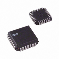
IC MULTIPLEXER DUAL 8X1 28PLCC
Manufacturer
Analog Devices Inc
Series
LC²MOSr
Type
Analog Multiplexerr
Datasheet
1.ADG406BNZ.pdf
(20 pages)
Specifications of ADG407BPZ
Function
Multiplexer
Circuit
2 x 8:1
On-state Resistance
80 Ohm
Voltage Supply Source
Single Supply
Voltage - Supply, Single/dual (±)
5V, 12V
Current - Supply
100µA
Operating Temperature
-40°C ~ 85°C
Mounting Type
Surface Mount
Package / Case
28-LCC (J-Lead)
No. Of Circuits
2
Supply Current
100µA
On State Resistance Max
50ohm
Supply Voltage Range
10.8V To 13.2V, ± 13.5V To ± 16.5V
Operating Temperature Range
-40°C To +85°C
Multiplexer Configuration
Dual 8:1
Number Of Inputs
16
Number Of Outputs
2
Number Of Channels
2
Analog Switch On Resistance
125@10.8VOhm
Analog Switch Turn On Time
240ns
Analog Switch Turn Off Time
180ns
Package Type
PLCC
Power Supply Requirement
Single/Dual
Single Supply Voltage (typ)
12V
Single Supply Voltage (max)
25V
Dual Supply Voltage (typ)
±15V
Dual Supply Voltage (max)
±22V
Mounting
Surface Mount
Pin Count
28
Operating Temp Range
-40C to 85C
Operating Temperature Classification
Industrial
Package
28PLCC
Maximum On Resistance
125@10.8V Ohm
Maximum Propagation Delay Bus To Bus
150@±15V|220@12V ns
Maximum High Level Output Current
20 mA
Multiplexer Architecture
8:1
Maximum Turn-off Time
180@12V ns
Maximum Turn-on Time
240@12V ns
Power Supply Type
Single|Dual
Lead Free Status / RoHS Status
Lead free / RoHS Compliant
Lead Free Status / RoHS Status
Lead free / RoHS Compliant, Lead free / RoHS Compliant
Available stocks
Company
Part Number
Manufacturer
Quantity
Price
Company:

Part Number:
ADG407BPZ
Manufacturer:
Analog Devices Inc
Quantity:
10 000
Part Number:
ADG407BPZ
Manufacturer:
ADI/亚德诺
Quantity:
20 000


ADG426 TIMING DIAGRAMS
Figure 4 shows the timing sequence for latching the switch
address and enable inputs. The latches are level sensitive;
therefore, while WR is held low, the latches are transparent and
the switches respond to the address and enable inputs. This
input data is latched on the rising edge of WR .
Figure 4. Timing Sequence for Latching the Switch Address and Enable Inputs
A0, A1, A2, (A3)
WR
EN
3V
0V
3V
0V
50%
2V
t
W
t
S
50%
0.8V
t
H
Rev. B | Page 7 of 20
Figure 5 shows the reset pulse width, t
time, t
Note that all digital input signals rise and fall times are
measured from 10% to 90% of 3 V; t
OUTPUT
SWITCH
OFF
( RS ).
RS
Figure 5. Reset Pulse Width and Reset Turn Off Time
3V
0V
V
0V
0
ADG406/ADG407/ADG426
50%
R
t
OFF
t
= t
rs
W
, and the reset turn off
(RS)
F
= 20 ns.
50%
0.8V
0
Related parts for ADG407BPZ
Image
Part Number
Description
Manufacturer
Datasheet
Request
R

Part Number:
Description:
±1.7g Dual-Axis IMEMS Accelerometer Evaluation Board
Manufacturer:
Analog Devices Inc
Datasheet:

Part Number:
Description:
Inertial Sensor Evaluation System
Manufacturer:
Analog Devices Inc
Datasheet:
Part Number:
Description:
Manufacturer:
Analog Devices Inc
Datasheet:
Part Number:
Description:
Manufacturer:
Analog Devices Inc
Datasheet:
Part Number:
Description:
Manufacturer:
Analog Devices Inc
Datasheet:
Part Number:
Description:
Manufacturer:
Analog Devices Inc
Datasheet:
Part Number:
Description:
Manufacturer:
Analog Devices Inc
Datasheet:
Part Number:
Description:
Manufacturer:
Analog Devices Inc
Datasheet:
Part Number:
Description:
Manufacturer:
Analog Devices Inc
Datasheet:
Part Number:
Description:
Manufacturer:
Analog Devices Inc
Datasheet:
Part Number:
Description:
Manufacturer:
Analog Devices Inc
Datasheet:
Part Number:
Description:
Manufacturer:
Analog Devices Inc
Datasheet:
Part Number:
Description:
Manufacturer:
Analog Devices Inc
Datasheet: