MC74HC4066ANG ON Semiconductor, MC74HC4066ANG Datasheet - Page 11
MC74HC4066ANG
Manufacturer Part Number
MC74HC4066ANG
Description
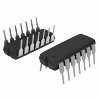
IC MUX/DEMUX QUAD 1X1 14DIP
Manufacturer
ON Semiconductor
Series
74HCr
Type
Analog Switchr
Datasheet
1.MC74HC4066ANG.pdf
(16 pages)
Specifications of MC74HC4066ANG
Function
Multiplexer/Demultiplexer
Circuit
4 x 1:1
On-state Resistance
100 Ohm
Voltage Supply Source
Dual Supply
Voltage - Supply, Single/dual (±)
±2 V ~ 12 V
Current - Supply
40µA
Operating Temperature
-55°C ~ 125°C
Mounting Type
Through Hole
Package / Case
14-DIP (0.300", 7.62mm)
Multiplexer Configuration
Quad SPST
Number Of Inputs
4
Number Of Outputs
4
Number Of Channels
4
Analog Switch On Resistance
120@4.5VOhm
Analog Switch Turn On Time
80ns
Analog Switch Turn Off Time
80ns
Package Type
PDIP
Power Supply Requirement
Single
Single Supply Voltage (min)
2V
Single Supply Voltage (typ)
3/5/9V
Single Supply Voltage (max)
12V
Dual Supply Voltage (min)
Not RequiredV
Dual Supply Voltage (typ)
Not RequiredV
Dual Supply Voltage (max)
Not RequiredV
Power Dissipation
750mW
Mounting
Through Hole
Pin Count
14
Operating Temp Range
-55C to 125C
Operating Temperature Classification
Military
Lead Free Status / RoHS Status
Lead free / RoHS Compliant
Other names
MC74HC4066ANGOS
Available stocks
Company
Part Number
Manufacturer
Quantity
Price
Company:

Part Number:
MC74HC4066ANG
Manufacturer:
ON
Quantity:
2 897


levels, V
recognized as a logic low. Unused analog inputs/outputs
may be left floating (not connected). However, it is
advisable to tie unused analog inputs and outputs to V
GND through a low value resistor. This minimizes crosstalk
and feedthrough noise that may be picked−up by the unused
I/O pins.
the supply voltages V
voltage should not exceed V
analog voltage should not go below GND. In the example
+ 12 V
The ON/OFF Control pins should be at V
The maximum analog voltage swings are determined by
0 V
CC
APPLICATION INFORMATION
being recognized as logic high and GND being
ANALOG I/O
Figure 16. 12 V Application
CC
and GND. The positive peak analog
SELECTED
CONTROL
INPUT
7
CC
ON
. Similarly, the negative peak
14
−10
−20
−30
−40
−50
−60
−70
−80
−90
0
ANALOG O/I
V
1.0
CC
Figure 15. Plot, Harmonic Distortion
CC
OTHER CONTROL
= 12 V
(V
or GND logic
CC
FUNDAMENTAL FREQUENCY
INPUTS
OR GND)
http://onsemi.com
CC
+ 12 V
0 V
or
FREQUENCY (kHz)
11
2.0
below, the difference between V
Therefore, using the configuration in Figure 16, a maximum
analog signal of twelve volts peak−to−peak can be
controlled.
are anticipated on the analog channels, external diodes (Dx)
are recommended as shown in Figure 17. These diodes
should be small signal, fast turn−on types able to absorb the
maximum anticipated current surges during clipping. An
alternate method would be to replace the Dx diodes with
Mosorbs (Mosorb™ is an acronym for high current surge
protectors). Mosorbs are fast turn−on devices ideally suited
for precise DC protection with no inherent wear out
mechanism.
When voltage transients above V
DEVICE
SOURCE
Figure 17. Transient Suppressor Application
V
CC
D
D
x
x
V
3.0
CC
SELECTED
CONTROL
INPUT
7
ON
CC
16
and GND is twelve volts.
CC
V
and/or below GND
CC
OTHER CONTROL
(V
CC
INPUTS
D
D
x
x
OR GND)
Related parts for MC74HC4066ANG
Image
Part Number
Description
Manufacturer
Datasheet
Request
R

Part Number:
Description:
ON Semiconductor [VOLTAGE REGULATOR]
Manufacturer:
ON Semiconductor
Datasheet:
Part Number:
Description:
357-036-542-201 CARDEDGE 36POS DL .156 BLK LOPRO
Manufacturer:
ON Semiconductor
Datasheet:
Part Number:
Description:
357-036-542-201 CARDEDGE 36POS DL .156 BLK LOPRO
Manufacturer:
ON Semiconductor
Datasheet:
Part Number:
Description:
357-036-542-201 CARDEDGE 36POS DL .156 BLK LOPRO
Manufacturer:
ON Semiconductor
Datasheet:
Part Number:
Description:
357-036-542-201 CARDEDGE 36POS DL .156 BLK LOPRO
Manufacturer:
ON Semiconductor
Datasheet:
Part Number:
Description:
357-036-542-201 CARDEDGE 36POS DL .156 BLK LOPRO
Manufacturer:
ON Semiconductor
Datasheet:
Part Number:
Description:
357-036-542-201 CARDEDGE 36POS DL .156 BLK LOPRO
Manufacturer:
ON Semiconductor
Datasheet:
Part Number:
Description:
357-036-542-201 CARDEDGE 36POS DL .156 BLK LOPRO
Manufacturer:
ON Semiconductor
Datasheet:
Part Number:
Description:
357-036-542-201 CARDEDGE 36POS DL .156 BLK LOPRO
Manufacturer:
ON Semiconductor
Datasheet:
Part Number:
Description:
357-036-542-201 CARDEDGE 36POS DL .156 BLK LOPRO
Manufacturer:
ON Semiconductor
Datasheet:
Part Number:
Description:
357-036-542-201 CARDEDGE 36POS DL .156 BLK LOPRO
Manufacturer:
ON Semiconductor
Datasheet:
Part Number:
Description:
Manufacturer:
ON Semiconductor
Datasheet:
Part Number:
Description:
Manufacturer:
ON Semiconductor
Datasheet:
Part Number:
Description:
Manufacturer:
ON Semiconductor
Datasheet: