LME49600TS/NOPB National Semiconductor, LME49600TS/NOPB Datasheet
LME49600TS/NOPB
Specifications of LME49600TS/NOPB
LME49600TS


Related parts for LME49600TS/NOPB

LME49600TS/NOPB Summary of contents
Page 1
... V pin. EE The LME49600 is fully protected through internal current limit and thermal shutdown. Functional Block Diagram FIGURE 1. Simplified Circuit Diagram (Note: I Boomer® registered trademark of National Semiconductor Corporation. © 2008 National Semiconductor Corporation Key Specifications ■ Low THD OUT ■ ...
Page 2
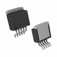
Connection Diagrams www.national.com Top View Order Number LME49600TS See NS Package Number TS5B 30029832 Top View U — Wafer fabrication code Z — Assembly plant XY — 2 Digit date code TT — Lot traceability 2 300298a0 ...
Page 3
... Absolute Maximum Ratings If Military/Aerospace specified devices are required, please contact the National Semiconductor Sales Office/ Distributors for availability and specifications. Supply Voltage ESD Ratings(Note 4) ESD Ratings (Note 5) Storage Temperature Junction Temperature Thermal Resistance θ JC System Electrical Characteristics for LME49600 f = 1kHz, unless otherwise specified. Typicals and limits apply for T ...
Page 4
Symbol Parameter V Voltage Output OUT I Output Current OUT I Short Circuit Output Current OUT-SC I Input Bias Current B Z Input Impedance IN V Offset Voltage OS V /°C Offset Voltage vs Temperature OS Note 1: All voltages ...
Page 5
Typical Performance Characteristics Gain vs Frequency vs Quiescent Current Gain vs Frequency vs Power Supply Voltage Wide BW Mode Phase vs Frequency vs Quiescent Current 30029899 Phase vs Frequency vs Supply Voltage Wide BW Mode 30029898 5 30029881 30029880 www.national.com ...
Page 6
Gain vs Frequency vs Power Supply Voltage Low I Mode Q Gain vs Frequency vs R Wide BW Mode Gain vs Frequency vs R Low I Mode Q www.national.com Phase vs Frequency vs Supply Voltage 30029897 Phase vs Frequency vs ...
Page 7
Gain vs Frequency vs C LOAD Wide BW Mode 30029894 Gain vs Frequency vs C LOAD Low I Mode Q 30029893 +PSRR vs Frequency V = ±15V, Wide BW Mode S 30029891 Phase vs Frequency vs C Wide BW Mode ...
Page 8
Frequency V = ±15V, Wide BW Mode S Quiescent Current vs Bandwidth Control Resistance High BW Noise Curve www.national.com +PSRR vs Frequency V = ±15V, Low I S 30029892 THD+N vs Output Voltage V = ±15V ...
Page 9
Typical Application Diagram FIGURE 2. High Performance, High Fidelity LME49600 Audio Buffer Application DISTORTION MEASUREMENTS The vanishingly low residual distortion produced by LME49710/LME49600 is below the capabilities of all com- mercially available equipment. This makes distortion mea- surements just slightly ...
Page 10
Application Information HIGH PERFORMANCE, HIGH FIDELITY HEADPHONE AMPLIFIER The LME49600 is the ideal solution for high output, high per- formance high fidelity head phone amplifiers. When placed in the feedback loop of the LME49710, LME49720 or LME49740 High Performance, High ...
Page 11
FIGURE 4. LME49600 delivers high output current for this high performance headphone amplifier 11 30029858 www.national.com ...
Page 12
AUDIO BUFFERS Audio buffers or unity-gain followers, have large current gain and a voltage gain of one. Audio buffers serve many applica- tions that require high input impedance, low output impedance and high output current. They also offer constant gain ...
Page 13
LOAD IMPEDANCE The LME49600 is stable under any capacitive load when driv source that has an impedance of 50Ω or less. When driving capacitive loads, any overshoot that is present on the output signal can be reduced ...
Page 14
FIGURE 7. Thermal Resistance for 5 lead TO–263 Package Mounted on 1oz. Copper A copper plane may be placed directly beneath the tab. Ad- ditionally, a matching plane can be placed on the opposite side plane is placed ...
Page 15
Examining the Copper Area vs. θ plot indicates that a ther- JA mal resistance of 50°C/W is possible with a 12in layer of 1oz copper. Other solutions include using two layers of 1oz copper or the use of 2oz copper. ...
Page 16
FIGURE 8. High Speed Positive and Negative Regulator www.national.com 30029844 16 ...
Page 17
Revision History Rev Date 1.0 01/15/08 1.01 01/16/08 1.02 02/07/08 1.03 03/28/08 Description Initial release. Edited specification table. Edited applications information. Text edits. 17 www.national.com ...
Page 18
Physical Dimensions www.national.com inches (millimeters) unless otherwise noted Order Number LME49600TS See NS Package TS5B 18 ...
Page 19
Notes 19 www.national.com ...
Page 20
... For more National Semiconductor product information and proven design tools, visit the following Web sites at: Products Amplifiers www.national.com/amplifiers Audio www.national.com/audio Clock Conditioners www.national.com/timing Data Converters www.national.com/adc Displays www.national.com/displays Ethernet www.national.com/ethernet Interface www.national.com/interface LVDS www.national.com/lvds Power Management www.national.com/power Switching Regulators www.national.com/switchers LDOs www ...