1-1926730-8 TE Connectivity, 1-1926730-8 Datasheet - Page 5
1-1926730-8
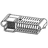
Manufacturer Part Number
1-1926730-8
Description
Manufacturer
TE Connectivity
Specifications of 1-1926730-8
Pcb Mount Alignment
With
Pcb Mount Retention
With
Pcb Mounting Orientation
Right Angle
Make First / Break Last
Yes
Product Line
MINIPAK HDL
Ul File Number
E28476
Termination Method To Pc Board
Through Hole - Press Fit
Pcb Mount Alignment Type
Boardlocks
Sealed
No
Number Of Power Positions
8
Operating Voltage Reference
AC
Operating Voltage (vac)
250
Hot Pluggable
No
Tail Length (mm [in])
3.3 [0.13]
Tail Orientation
In-line
Profile Height (y-axis) (mm [in])
8.00 [0.315]
Number Of Signal Positions
25
Number Of Positions
33
Pcb Mount Retention Type
Boardlock(s)
Selectively Loaded
Yes
Centerline (mm [in])
2.00 [0.079]
Centerline, Power Contacts (mm [in])
2.75 [0.108]
Underplate Material Thickness (µm [?in])
1.27 [50.000]
Length (x-axis) (mm [in])
46.21 [1.820]
Width (z-axis) (mm [in])
26.50 [1.040]
Number Of Rows
1
Mating Retention
Without
Tail Plating Material
Matte Tin
Contact Type
Pin
Contact Base Material
Copper
Contact Plating, Mating Area, Material
Gold or Palladium Nickel or Performance Based
Contact Plating, Mating Area, Thickness (µm [?in])
0.762 [30]
Tail Plating, Thickness (µm [?in])
0.5 [20]
Underplate Material
Nickel
Contact Design
Single Beam
Connector Style
Plug
Mating Alignment
With
Housing Material
Crystal Polymer
Ul Flammability Rating
UL 94V-0
Housing Color
Black
Mating Alignment Type
Passive Guide
Connector Contact Configuration (no. Of Pos./type)
25/Signal, 8/AC Power
Custom Configurable
No
Rohs/elv Compliance
RoHS compliant, ELV compliant
Lead Free Solder Processes
Wave solder capable to 240°C, Wave solder capable to 260°C, Wave solder capable to 265°C
Rohs/elv Compliance History
Always was RoHS compliant
Agency/standard
UL, CSA
Ul Rating
Recognized
Ul Voltage Rating (vac)
250
Csa Certified
Yes
Operating Temperature (°c [°f])
-40 – +125 [-40 – +257]
Pcb Thickness, Recommended (mm [in])
1.40 [0.055]
Applies To
Printed Circuit Board
Board-to-board Configuration
Co-Planar
Contact Transmits (typical Application)
Signal (Data)/ Power
Application Use
Board-to-Board
Pick And Place Cover
Without
Packaging Method
Tube


Static load, transverse.
Contact retention.
Minute disturbance.
Com ponent heat resistance to wave
soldering.
Therm al shock.
Hum idity/tem perature cycling.
Rev B
Test Description
F1 = 100 N
F2 = 75 N
F3 = 50 N
No displacem ent of connector on
PCB likely to im pair norm al
operation.
See Note.
Signal contacts:
2 N m inim um in the m ating
direction.
9.5 N m inim um for pins in the
unm ating direction.
5 N m inim um for receptacles in the
unm ating direction.
Power contacts:
0.1 m m m axim um axial
displacem ent.
See Note.
See Note.
See Note.
See Note.
See Note.
Figure 3 (continued)
ENVIRONMENTAL
Requirem ent
Apply specified force in m iddle of
the specim en approxim ately 6 and
11 m m above the PCB.
See Figure 5.
Tyco Electronics 109-30-1.
Signal contacts:
Apply axial force of 2 N to pin and
receptacle contacts in the m ating
direction at a m axim um rate of 2.54
m m per m inute.
Apply axial force of 9.5 N (pin) and
5 N (receptacle) to pin contacts in
the unm ating direction at a
m axim um rate of 2.54 m m per
m inute.
Power contacts:
Apply axial force of 10 N to pin
contacts in the unm ating direction at
a m axim um rate of 2.54 m m per
m inute and hold for 5 seconds.
Apply axial force of 5 N to pin
contacts in the m ating direction at a
m axim um rate of 2.54 m m per
m inute and hold for 5 seconds.
Apply axial force of 5 N to
receptacle contacts in both the
m ating (against the tip of the pin)
and unm ating (against the back of
the contact) directions at a
m axim um rate of 2.54 m m per
m inute and hold for 5 seconds.
Unm ate and m ate each connector
pair a distance of approxim ately 0.1
m m .
Tyco Electronics 109-202,
Condition B.
EIA-364-32.
Subject unm ated specim ens to 5
cycles between -40 and 125 C with
30 m inute dwells at tem perature
extrem es and less than 1 m inute
transition between tem peratures.
EIA-364-31, Method III.
Subject unm ated specim ens to 10
cycles (10 days) between 25 and
65 C at 80 to 100% RH.
Procedure
108-2325
5 of 9
Related parts for 1-1926730-8
Image
Part Number
Description
Manufacturer
Datasheet
Request
R

Part Number:
Description:
PLUG & SOCKET HOUSING, PLUG, NYLON
Manufacturer:
TE Connectivity
Datasheet:

Part Number:
Description:
PLUG & SOCKET HOUSING, PLUG, NYLON
Manufacturer:
TE Connectivity
Datasheet:
Part Number:
Description:
PLUG & SOCKET HOUSING, PLUG, NYLON
Manufacturer:
TE Connectivity
Datasheet:

Part Number:
Description:
PLUG & SOCKET HOUSING, RECEPTACLE, NYLON
Manufacturer:
TE Connectivity
Datasheet:
Part Number:
Description:
PLUG & SOCKET HOUSING, PLUG, NYLON
Manufacturer:
TE Connectivity
Datasheet:

Part Number:
Description:
PLUG & SOCKET HOUSING, RECEPTACLE, NYLON
Manufacturer:
TE Connectivity
Datasheet:
Part Number:
Description:
PLUG & SOCKET HOUSING, RECEPTACLE, NYLON
Manufacturer:
TE Connectivity
Datasheet:

Part Number:
Description:
HEADER, 5WAY
Manufacturer:
TE Connectivity
Datasheet:

Part Number:
Description:
PLUG & SOCKET HOUSING, PLUG, NYLON
Manufacturer:
TE Connectivity
Datasheet:
Part Number:
Description:
PLUG & SOCKET HOUSING, PLUG, NYLON
Manufacturer:
TE Connectivity
Datasheet:

Part Number:
Description:
PLUG & SOCKET HOUSING, RECEPTACLE, NYLON
Manufacturer:
TE Connectivity
Datasheet:
Part Number:
Description:
PLUG & SOCKET HOUSING, RECEPTACLE, NYLON
Manufacturer:
TE Connectivity
Datasheet:

Part Number:
Description:
PLUG & SOCKET HOUSING, PLUG, NYLON
Manufacturer:
TE Connectivity
Datasheet:
Part Number:
Description:
PLUG & SOCKET HOUSING, RECEPTACLE, NYLON
Manufacturer:
TE Connectivity
Datasheet:
Part Number:
Description:
PLUG & SOCKET HOUSING, PLUG, NYLON
Manufacturer:
TE Connectivity
Datasheet: