LM2901NG ON Semiconductor, LM2901NG Datasheet - Page 6
LM2901NG
Manufacturer Part Number
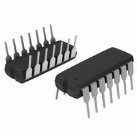
LM2901NG
Description
IC COMP QUAD SGL SUPPLY 14DIP
Manufacturer
ON Semiconductor
Type
General Purposer
Specifications of LM2901NG
Number Of Elements
4
Output Type
CMOS, Open-Collector, TTL
Voltage - Supply
3 V ~ 36 V, ±1.5 V ~ 18 V
Mounting Type
Through Hole
Package / Case
14-DIP (0.300", 7.62mm)
Number Of Channels
4 Channels
Response Time
1.3 us
Offset Voltage (max)
7 mV
Input Bias Current (max)
250 nA
Supply Voltage (max)
36 V
Supply Voltage (min)
3 V
Supply Current (max)
2 mA
Maximum Power Dissipation
1000 mW
Maximum Operating Temperature
+ 105 C
Mounting Style
Through Hole
Minimum Operating Temperature
- 40 C
Amplifier Type
Comparator
Current, Input Bias
25 nA
Current, Input Offset
±5 nA
Current, Supply
1 mA
Number Of Amplifiers
Quad
Package Type
PDIP-14
Power Dissipation
1 W
Temperature, Operating, Range
-40 to +105 °C
Voltage, Gain
100 V/mV
Voltage, Input Offset
±2 mVDC
Voltage, Supply
±18 VDC
Comparator Type
General Purpose
No. Of Comparators
4
Ic Output Type
CMOS, TTL
Supply Current
1mA
Supply Voltage Range
3V To 36V
Amplifier Case Style
DIP
No. Of Pins
14
Rohs Compliant
Yes
Lead Free Status / RoHS Status
Lead free / RoHS Compliant
Other names
LM2901NGOS
Available stocks
Company
Part Number
Manufacturer
Quantity
Price

Part Number:
LM2901NG
Manufacturer:
ON/安森美
Quantity:
20 000


bandwidth characteristics. This gives the device oscillation
tendencies if the outputs are capacitively coupled to the
inputs via stray capacitance. This oscillation manifests itself
during output transitions (V
situation input resistors < 10 kW should be used. The
These quad comparators feature high gain, wide
V
in
D1 prevents input from going negative by more than 0.6 V.
Figure 9. Zero Crossing Detector
8.2 k
R1
D1
R3 ≤
R5
10
220 k
6.8 k
(Single Supply)
R2
R4
for small error in zero crossing
R1 + R2 = R3
220 k
15 k
R5
R3
OL
to V
*
)
+15 V
OH
10 M
). To alleviate this
APPLICATIONS INFORMATION
10 k
V
O
http://onsemi.com
6
V
in
addition of positive feedback (< 10 mV) is also
recommended. It is good design practice to ground all
unused input pins.
voltages without damaging the comparator’s inputs.
Voltages more negative than −300 mV should not be used.
Differential input voltages may be larger than supply
V
in(min)
Figure 10. Zero Crossing Detector
≈ 0.4 V peak for 1% phase distortion (Dq).
*
+
V
V
CC
EE
(Split Supplies)
10 k
V
O
V
V
V
V
in
CC
O
EE
V
Dq
in(min)
q
q
Related parts for LM2901NG
Image
Part Number
Description
Manufacturer
Datasheet
Request
R

Part Number:
Description:
ON Semiconductor [VOLTAGE REGULATOR]
Manufacturer:
ON Semiconductor
Datasheet:
Part Number:
Description:
357-036-542-201 CARDEDGE 36POS DL .156 BLK LOPRO
Manufacturer:
ON Semiconductor
Datasheet:
Part Number:
Description:
357-036-542-201 CARDEDGE 36POS DL .156 BLK LOPRO
Manufacturer:
ON Semiconductor
Datasheet:
Part Number:
Description:
357-036-542-201 CARDEDGE 36POS DL .156 BLK LOPRO
Manufacturer:
ON Semiconductor
Datasheet:
Part Number:
Description:
357-036-542-201 CARDEDGE 36POS DL .156 BLK LOPRO
Manufacturer:
ON Semiconductor
Datasheet:
Part Number:
Description:
357-036-542-201 CARDEDGE 36POS DL .156 BLK LOPRO
Manufacturer:
ON Semiconductor
Datasheet:
Part Number:
Description:
357-036-542-201 CARDEDGE 36POS DL .156 BLK LOPRO
Manufacturer:
ON Semiconductor
Datasheet:
Part Number:
Description:
357-036-542-201 CARDEDGE 36POS DL .156 BLK LOPRO
Manufacturer:
ON Semiconductor
Datasheet:
Part Number:
Description:
357-036-542-201 CARDEDGE 36POS DL .156 BLK LOPRO
Manufacturer:
ON Semiconductor
Datasheet:
Part Number:
Description:
357-036-542-201 CARDEDGE 36POS DL .156 BLK LOPRO
Manufacturer:
ON Semiconductor
Datasheet:
Part Number:
Description:
357-036-542-201 CARDEDGE 36POS DL .156 BLK LOPRO
Manufacturer:
ON Semiconductor
Datasheet:
Part Number:
Description:
Manufacturer:
ON Semiconductor
Datasheet:
Part Number:
Description:
Manufacturer:
ON Semiconductor
Datasheet:
Part Number:
Description:
Manufacturer:
ON Semiconductor
Datasheet: