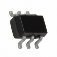
NC7WV07P6X Fairchild Semiconductor, NC7WV07P6X Datasheet - Page 5

NC7WV07P6X
Manufacturer Part Number
NC7WV07P6X
Description
IC BUFF DL ULP-A O/DRAIN SC706
Manufacturer
Fairchild Semiconductor
Series
7WVr
Specifications of NC7WV07P6X
Logic Type
Buffer/Line Driver, Non-Inverting with Open Drain
Number Of Elements
2
Number Of Bits Per Element
1
Voltage - Supply
0.9 V ~ 3.6 V
Operating Temperature
-40°C ~ 85°C
Mounting Type
Surface Mount
Package / Case
SC-70-6, SC-88, SOT-363
Logic Family
NC7WV
Number Of Channels Per Chip
Dual
Polarity
Non-Inverting
Supply Voltage (max)
3.6 V
Supply Voltage (min)
0.9 V
Maximum Operating Temperature
85 C
Mounting Style
SMD/SMT
High Level Output Current
- 24 mA
Input Bias Current (max)
0.9 uA
Low Level Output Current
24 mA
Minimum Operating Temperature
- 40 C
Number Of Lines (input / Output)
3
Output Type
Open Drain
Propagation Delay Time
6 ns at 1.65 V to 1.95 V, 3.6 ns at 2.3 V to 2.7 V, 3.3 ns at 2.7 V to 3.6 V
Logic Device Type
Buffer, Non Inverting
Supply Voltage Range
0.9V To 3.6V
Logic Case Style
SC-70
No. Of Pins
6
Operating Temperature Range
-40°C To +85°C
Filter Terminals
SMD
Rohs Compliant
Yes
Lead Free Status / RoHS Status
Lead free / RoHS Compliant
Current - Output High, Low
-
Lead Free Status / Rohs Status
Lead free / RoHS Compliant
Available stocks
Company
Part Number
Manufacturer
Quantity
Price
Part Number:
NC7WV07P6X
Manufacturer:
FAIRCHILD/ن»™ç«¥
Quantity:
20 000
NC7WV07 Rev. 1.0.0
AC Electrical Characteristics
AC Loading and Waveforms
t
C
C
C
PZL
Symbol
IN
OUT
PD
, t
PLZ
Propagation Delay
Input Capacitance
Output Capacitance
Power Dissipation
Capacitance
Symbol
V
V
Parameter
mi
x
SIGNAL
TEST
Figure 2. Waveform for Inverting and Non-Inverting Functions
3.3V ± 0.3V
V
OL
1.5V
+ 0.3V
t
Input
Output
C
R
C
R
C
R
V
f = 10MHz
r
Conditions
U
U
U
I
L
L
L
= 3ns
V
DUT
= 0V or V
= 15pF,
= 15pF,
= 30pF,
V
= R
= R
= R
CC
OH
D
D
D
V
2.5V ± 0.2V 1.8V ± 0.15V 1.5V ± 0.1V
t
10%
PZL
1MΩ
2kΩ
500Ω
OL
Test
V
CC
, t
CC
+ 0.15V V
,
PLZ
30pF
t
/ 2
V
PZL
1.10 ≤ V
1.40 ≤ V
1.65 ≤ V
2.30 ≤ V
2.70 ≤ V
Figure 1. AC Test Circuit
mi
90%
0.90 to 3.60
50%
V
CC
0.90
OL
CC
CC
CC
CC
CC
0
0
t
W
V
(V)
1000Ω
CC
+ 0.15V
≤ 1.30
≤ 1.60
≤ 1.95
< 2.70
≤ 3.60
V
1000Ω
90%
V
CC
5
/ 2
mi
6V at V
× 2 at V
V
t
Min. Typ. Max.
PLZ
CC
2.0
1.0
1.0
0.7
0.5
–
–
–
10%
V
CC
Switch
OL
t
V
CC
f
+25°C
= 3.3 ± 0.3V;
= 3ns
CC
6.0
3.2
2.0
1.2
1.0
2.0
6.5
13
10
+ 0.1V
= 0.9V − 2.7V
V
V
/ 2
OPEN
GND
6.0V or V
X
CC
V
GND
CC
15.0
8.7
6.0
3.6
3.3
–
–
–
T
A
1.2 V ± 0.1V
V
V
=
OL
CC
−40°C to +85°C
CC
V
Min.
CC
1.0
1.0
1.0
0.6
0.4
+ 0.1V
x 2
–
–
–
/ 2
t
t
t
PLH
PZH
PZL
Max.
18.6
9.7
6.8
4.7
4.0
, t
, t
, t
–
–
–
V
PLZ
PHL
PHZ
OL
V
0.9V
CC
+ 0.1V
Units
pF
pF
pF
ns
/ 2
www.fairchildsemi.com
Number
Figure 1
Figure 2
Figure


