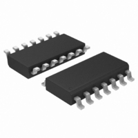
MC74LVX50DG ON Semiconductor, MC74LVX50DG Datasheet

MC74LVX50DG
Specifications of MC74LVX50DG
Related parts for MC74LVX50DG
MC74LVX50DG Summary of contents
Page 1
MC74LVX50 Hex Buffer The MC74LVX50 is an advanced high speed CMOS buffer fabricated with silicon gate CMOS technology. The internal circuit is composed of three stages, including a buffered output which provides high noise immunity and stable output. The inputs ...
Page 2
... Figure 1. Logic Diagram 14−Lead Pinout (Top View) ORDERING INFORMATION Device MC74LVX50DG MC74LVX50DR2G MC74LVX50DTG MC74LVX50DTR2G MC74LVX50MG MC74LVX50MELG †For information on tape and reel specifications, including part orientation and tape sizes, please refer to our Tape and Reel Packaging Specifications Brochure, BRD8011/D. *This package is inherently Pb−Free ...
Page 3
MAXIMUM RATINGS Symbol V DC Supply Voltage Input Voltage Output Voltage OUT I DC Input Diode Current Output Diode Current Output Sink Current OUT I DC Supply Current ...
Page 4
DC ELECTRICAL CHARACTERISTICS Î Î Î Î Î Î Î Î Î Î Î Î Î Î Î Î Î Î Î Î Î Î Î Î Î Î Symbol Parameter Î Î Î Î Î Î Î Î Î ...
Page 5
A t PLH 50 Figure 3. Switching Waveforms EMBOSSED CARRIER DIMENSIONS (See Notes 9 and 10) Tape Size Max 8 mm 4.35 mm 1.0 mm 1.5 mm 1.75 mm (0.179”) Min ...
Page 6
K t COVER SEE NOTE 11 FOR MACHINE REFERENCE ONLY INCLUDING DRAFT AND RADII CONCENTRIC AROUND MIN. TAPE AND COMPONENTS SHALL PASS AROUND RADIUS “R” WITHOUT DAMAGE BENDING RADIUS MAXIMUM COMPONENT ROTATION 10° TYPICAL ...
Page 7
MIN (0.06”) 20.2 mm MIN A (0.795”) FULL RADIUS Figure 7. Reel Dimensions REEL DIMENSIONS Tape Size T&R Suffix A Max 8 mm T1, T2 178 mm (7” T3, T4 330 mm (13” ...
Page 8
TAPE TRAILER (Connected to Reel Hub) CAVITY TOP TAPE NO COMPONENTS TAPE 160 mm MIN Figure 10. TSSOP and SOIC R2 Reel Configuration/Orientation TAPE UTILIZATION BY PACKAGE Tape Size COMPONENTS DIRECTION OF ...
Page 9
G −T− SEATING 14 PL PLANE 0.25 (0.010 PACKAGE DIMENSIONS SOIC−14 D SUFFIX CASE 751A−03 ISSUE 0.25 (0.010 ...
Page 10
K 14X REF 0.10 (0.004) 0.15 (0.006 L PIN 1 IDENT. 1 0.15 (0.006 −V− C 0.10 (0.004) −T− G SEATING D PLANE 14X 0.36 PACKAGE DIMENSIONS TSSOP−14 DT SUFFIX ...
Page 11
... Opportunity/Affirmative Action Employer. This literature is subject to all applicable copyright laws and is not for resale in any manner. PUBLICATION ORDERING INFORMATION LITERATURE FULFILLMENT: Literature Distribution Center for ON Semiconductor P.O. Box 5163, Denver, Colorado 80217 USA Phone: 303−675−2175 or 800−344−3860 Toll Free USA/Canada Fax: 303− ...


