LM2405T National Semiconductor, LM2405T Datasheet - Page 4
LM2405T
Manufacturer Part Number
LM2405T
Description
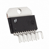
IC DRIVER MONOLITHIC TO-220-11
Manufacturer
National Semiconductor
Datasheet
1.LM2405T.pdf
(7 pages)
Specifications of LM2405T
Display Type
CRT
Current - Supply
18mA
Voltage - Supply
60 V ~ 85 V
Operating Temperature
-20°C ~ 100°C
Mounting Type
Through Hole
Package / Case
TO-220-11 (Bent and Staggered Leads)
Lead Free Status / RoHS Status
Contains lead / RoHS non-compliant
Interface
-
Configuration
-
Digits Or Characters
-
Other names
*LM2405T
Available stocks
Company
Part Number
Manufacturer
Quantity
Price

Part Number:
LM2405T
Manufacturer:
NS/国半
Quantity:
20 000
Company:
Part Number:
LM2405T(EM89DT)
Manufacturer:
NationalSemi
Quantity:
308


www.national.com
Application Hints
the supply pin as is practical (preferably less than
the supply pin). Additionally, a 10 µF to 100 µF electrolytic
capacitor should be connected from the supply pin to
ground. The electrolytic capacitor should also be placed rea-
sonably close to the LM2405’s supply pin. A 0.1 µF capacitor
should be connected from the bias pin, V
close as is practical to the part.
ARC PROTECTION
During normal CRT operation, internal arcing may occasion-
ally occur. Spark gaps of 200V to 300V at the cathodes will
limit the maximum voltage, but to a value that is much higher
than allowable on the LM2405. This fast, high voltage, high
energy pulse can damage the LM2405 output stage. The ad-
dition of clamp diodes D1 and D2 (as shown in Figure 7 ) will
help clamp the voltage at the output of the LM2405 to a safe
level. The clamp diodes should have a fast transient re-
sponse, high peak current rating, low series impedance and
low shunt capacitance. FDH400 or equivalent diodes are
recommended. Resistor R2 in Figure 7 limits the arcover
current while R1 limits the current into the LM2405 and re-
duces the power dissipation of the output transistors when
the output is stressed beyond the supply voltage. (Peaking
inductor Lp also helps protect the CRT driver from arc over.)
Having large value resistors for R1 and R2 would be desir-
able, but this has the effect of increasing rise and fall times.
For proper arc protection, it is important to not omit any of the
arc protection components shown in Figure 7 .
There are also ESD protection diodes built into the part. To
avoid damaging these diodes, do not apply an input voltage
from a low impedance source when the V
are held at ground potential.
IMPROVING RISE AND FALL TIMES
Because of an emitter follower output stage, the rise and fall
times of the LM2405 are relatively insensitive to capactive
loading. However, the series resistors R1 and R2 (see Fig-
ure 7 ) will increase the rise and fall times when driving the
CRT’s cathode which appears as a capacitive load. The ca-
pacitance at the cathode typically ranges from 8 pF to 12 pF.
To improve the rise and fall times at the cathode, a small in-
ductor is often used in series with the output of the amplifier.
The inductor L
response at the cathode, thus improving rise and fall times.
It also acts with the output load capacitance to form a low
pass filter, which reduces the amplitudes of high frequency
harmonics of the video signal, to lower radiated electromag-
netic interference. The inductor value is empirically deter-
mined and is dependent on the load. An inductor value of
0.22 µH is a good starting value. Note that excessive peak-
FIGURE 7. One Section of the LM2405 with Arc
Protection and Peaking Inductor L
P
in Figure 7 peaks the amplifier’s frequency
(Continued)
BB
BB
, to ground, as
and V
P
1
DS012682-8
CC
⁄
4
" from
pins
4
ing of the amplifier’s frequency response will increase the
overshoot. (Increasing the value of resistor R1 or R2 will re-
duce ringing and overshoot.)
EFFECT OF LOAD CAPACITANCE
The output rise and fall times will be slower than specified if
the load capacitance at the output is more than 8 pF, as
shown in Figure 8 .
The monitor designer should ensure that stray capacitance
applied to the LM2405 is as low as possible.
THERMAL CONSIDERATIONS
Power supply current increases as the input signal increases
and consequently power dissipation also increases.
The LM2405 cannot be used without heat sinking. Typical
“average” power dissipation with the device output voltage at
one half the supply voltage is 2.4W per channel for a total
dissipation of 7.2W package dissipation. Under white screen
conditions, i.e., 25V output, dissipation increases to 3.5W
per channel or 10.5W total. The LM2405 case temperature
must be maintained below 100˚C. If the maximum expected
ambient temperature is 50˚C, then a maximum heat sink
thermal resistance can be calculated:
This example assumes a typical CRT capacitive load and is
without a resistive load. Note that this thermal resistance
must be achieved when the heat sink is operating in the
monitor.
INPUT RESISTANCE
The LM2405 has a fixed resistor of 3000
each signal input pin to ground. In the Figure 2 Test Circuit,
the input DC voltage level, Vtest, must be adjusted, (to about
+3.5V) to allow for the voltage drop across the 1000
tor, to set the actual voltage at the input pins to +2.6V. In ac-
tual use in a monitor, the 1000
video preamp supplies the 2.6V offset.
PC BOARD LAYOUT CONSIDERATIONS
For optimum performance, an adequate ground plane, isola-
tion between channels, good supply bypassing and minimiz-
ing unwanted feedback are necessary. Also, the length of the
FIGURE 8. Effect of Load Capacitance on
Rise/Fall Time
resistor is not used and the
DS012682-9
connected from
resis-
Related parts for LM2405T
Image
Part Number
Description
Manufacturer
Datasheet
Request
R

Part Number:
Description:
Monolithic Triple 3 ns CRT Driver
Manufacturer:
National Semiconductor
Datasheet:
Part Number:
Description:
National Semiconductor [8-Bit D/A Converter]
Manufacturer:
National Semiconductor
Datasheet:
Part Number:
Description:
National Semiconductor [Media Coprocessor]
Manufacturer:
National Semiconductor
Datasheet:
Part Number:
Description:
Digitally Controlled Tone and Volume Circuit with Stereo Audio Power Amplifier, Microphone Preamp Stage and National 3D Sound
Manufacturer:
National Semiconductor
Datasheet:
Part Number:
Description:
Digitally Controlled Tone and Volume Circuit with Stereo Audio Power Amplifier, Microphone Preamp Stage and National 3D Sound
Manufacturer:
National Semiconductor
Datasheet:
Part Number:
Description:
AC97 Rev 2 Codec with Sample Rate Conversion and National 3D Sound
Manufacturer:
National Semiconductor
Part Number:
Description:
Manufacturer:
National Semiconductor
Datasheet:
Part Number:
Description:
Manufacturer:
National Semiconductor
Datasheet:
Part Number:
Description:
General Purpose, Low Voltage, Low Power, Rail-to-Rail Output Operational Amplifiers
Manufacturer:
National Semiconductor
Datasheet:
Part Number:
Description:
8-bit 20 MSPS flash A/D converter.
Manufacturer:
National Semiconductor
Datasheet:
Part Number:
Description:
Low Noise Quad Operational Amplifier
Manufacturer:
National Semiconductor
Datasheet:
Part Number:
Description:
Quad Differential Line Receivers
Manufacturer:
National Semiconductor
Datasheet:
Part Number:
Description:
Quad High Speed Trapezoidal? Bus Transceiver
Manufacturer:
National Semiconductor
Datasheet:
Part Number:
Description:
Dual Line Receiver
Manufacturer:
National Semiconductor
Datasheet: