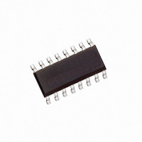
HCPL-316J-500E Avago Technologies US Inc., HCPL-316J-500E Datasheet - Page 26

HCPL-316J-500E
Manufacturer Part Number
HCPL-316J-500E
Description
OPTOCOUPLER 2CH 2.5A 16-SOIC
Manufacturer
Avago Technologies US Inc.
Datasheet
1.HCPL-316J-500E.pdf
(33 pages)
Specifications of HCPL-316J-500E
Configuration
High-Side
Package / Case
16-SOIC (0.300", 7.5mm Width)
Input Type
Differential
Delay Time
300ns
Current - Peak
2.5A
Number Of Configurations
1
Number Of Outputs
1
Voltage - Supply
4.5 V ~ 5.5 V
Operating Temperature
-40°C ~ 100°C
Mounting Type
Surface Mount
Fall Time
0.1 us
Rise Time
0.1 us
Isolation Voltage
3750 Vrms
Maximum Power Dissipation
1200 mW
Maximum Operating Temperature
+ 100 C
Minimum Operating Temperature
- 40 C
Lead Free Status / RoHS Status
Lead free / RoHS Compliant
High Side Voltage - Max (bootstrap)
-
Lead Free Status / Rohs Status
Lead free / RoHS Compliant
Other names
516-1777-2
HCPL-316J-500E
HCPL-316J-500E
Available stocks
Company
Part Number
Manufacturer
Quantity
Price
Company:
Part Number:
HCPL-316J-500E
Manufacturer:
AVAGO
Quantity:
3 200
Company:
Part Number:
HCPL-316J-500E
Manufacturer:
AGILENT
Quantity:
17
Part Number:
HCPL-316J-500E
Manufacturer:
AVAGO/安华高
Quantity:
20 000
Part Number:
HCPL-316J-500E/HCPL316J-500E
Manufacturer:
AVAGO/安华高
Quantity:
20 000
User-Configuration of the HCPL-316J Input Side
The V
variety of gate control and fault configurations pos-
sible, depending on the motor drive requirements. The
HCPL-316J has both inverting and non inverting gate
control inputs, an open collector fault output suitable
for wired ‘OR’ applications and an active low reset input.
Driving Input pf HCPL-316J in Non-Inverting/Inverting
Mode
The Gate Drive Voltage Output of the HCPL-316J can
be configured as inverting or non-inverting using the
V
non-inverting configuration is desired, V
by connecting it to GND1 and V
in Figure 69, when an inverting configuration is desired,
V
gled.
Local Shutdown, Local Reset
As shown in Figure 70, the fault output of each HCPL-
316J gate driver is polled separately, and the individual
reset lines are asserted low independently to reset the
motor controller after a fault condition.
Global-Shutdown, Global Reset
As shown in Figure 71, when configured for inverting op-
eration, the HCPL-316J can be configured to shutdown
automatically in the event of a fault condition by tying
the FAULT output to V
open collector FAULT outputs of each HCPL-316J can be
wire ‘OR’ed together on a common fault bus, forming a
single fault bus for interfacing directly to the micro-con-
troller. When any of the six gate drivers detects a fault,
the fault output signal will disable all six HCPL-316J gate
drivers simultaneously and thereby provide protection
against further catastrophic failures.
26
IN–
IN+
is held high by connecting it to V
and V
IN+
, V
IN-
IN+
, FAULT and RESET input pins make a wide
inputs. As shown in Figure 68, when a
IN+
. For high reliability drives, the
IN+
is toggled. As shown
CC1
and V
IN–
is held low
IN–
is tog-
Figure 68. Typical input configuration, noninverting.
Figure 69. Typical Input Configuration, Inverting.
Figure 70. Local shutdown, local reset configuration.
μC
μC
μC
+
–
+
–
+
–
1
2
3
4
5
6
7
8
1
2
3
4
5
6
7
8
1
2
3
4
5
6
7
8
V
V
V
GND1
RESET
FAULT
V
V
IN+
IN-
CC1
LED1+
LED1-
V
V
V
GND1
RESET
FAULT
V
V
V
V
V
GND1
RESET
FAULT
V
V
IN+
IN-
CC1
LED1+
LED1-
IN+
IN-
CC1
LED1+
LED1-
HCPL-316J
HCPL-316J
HCPL-316J


