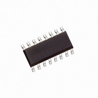
HCPL-316J Avago Technologies US Inc., HCPL-316J Datasheet - Page 24

HCPL-316J
Manufacturer Part Number
HCPL-316J
Description
OPTOCOUPLER GATE DRV 2A 16-SOIC
Manufacturer
Avago Technologies US Inc.
Datasheet
1.HCPL-316J-500E.pdf
(33 pages)
Specifications of HCPL-316J
Configuration
High-Side
Input Type
Differential
Delay Time
300ns
Current - Peak
2.5A
Number Of Configurations
1
Number Of Outputs
1
Voltage - Supply
4.5 V ~ 5.5 V
Operating Temperature
-40°C ~ 100°C
Mounting Type
Surface Mount
Package / Case
16-SOIC (0.300", 7.5mm Width)
No. Of Channels
1
Isolation Voltage
3.75kV
Optocoupler Output Type
Gate Drive
Input Current
22mA
Output Voltage
30V
Opto Case Style
SOIC
No. Of Pins
16
Propagation Delay Low-high
0.5µs
Lead Free Status / RoHS Status
Contains lead / RoHS non-compliant
High Side Voltage - Max (bootstrap)
-
Lead Free Status / RoHS Status
Contains lead / RoHS non-compliant, Contains lead / RoHS non-compliant
Other names
516-1130-5
Available stocks
Company
Part Number
Manufacturer
Quantity
Price
Company:
Part Number:
HCPL-316J
Manufacturer:
AVAGO
Quantity:
20 700
Company:
Part Number:
HCPL-316J
Manufacturer:
AD
Quantity:
1 939
Part Number:
HCPL-316J
Manufacturer:
AGILENT
Quantity:
20 000
Company:
Part Number:
HCPL-316J#500
Manufacturer:
AGILENT
Quantity:
3 169
Part Number:
HCPL-316J#500
Manufacturer:
AGILENT
Quantity:
20 000
Company:
Part Number:
HCPL-316J-000E
Manufacturer:
KOITECH
Quantity:
713
Company:
Part Number:
HCPL-316J-000E
Manufacturer:
AVAGO
Quantity:
21 000
Part Number:
HCPL-316J-000E
Manufacturer:
AVAGO/安华高
Quantity:
20 000
Part Number:
HCPL-316J-500E
Manufacturer:
AVAGO/安华高
Quantity:
20 000
Part Number:
HCPL-316J-500E/HCPL316J-500E
Manufacturer:
AVAGO/安华高
Quantity:
20 000
Behavioral Circuit Schematic
The functional behavior of the HCPL-316J is rep-
resented by the logic diagram in Figure 64
which fully describes the interaction and se-
quence of internal and external signals in the
HCPL-316J.
Input IC
In the normal switching mode, no output fault has been
detected, and the low state of the fault latch allows the
input signals to control the signal LED. The fault output
is in the open-collector state, and the state of the Reset
pin does not affect the control of the IGBT gate. When a
fault is detected, the FAULT output and signal input are
both latched. The fault output changes to an active low
state, and the signal LED is forced off (output LOW). The
latched condition will persist until the Reset pin is pulled
low.
24
Figure 64. Behavioral circuit schematic.
V
V
V
GND (4)
FAULT (6)
RESET (5)
IN+
IN–
CC1
(2)
(1)
(3)
DELAY
R S
Q
LED
FAULT
Output IC
Three internal signals control the state of the driver out-
put: the state of the signal LED, as well as the UVLO and
Fault signals. If no fault on the IGBT collector is detected,
and the supply voltage is above the UVLO threshold,
the LED signal will control the driver output state. The
driver stage logic includes an interlock to ensure that the
pull-up and pull-down devices in the output stage are
never on at the same time. If an undervoltage condition
is detected, the output will be actively pulled low by the
50x DMOS device, regardless of the LED state. If an IGBT
desaturation fault is detected while the signal LED is on,
the Fault signal will latch in the high state. The triple dar-
lington AND the 50x DMOS device are disabled, and a
smaller 1x DMOS pull-down device is activated to slowly
discharge the IGBT gate. When the output drops below
two volts, the 50x DMOS device again turns on, clamp-
ing the IGBT gate firmly to Vee. The Fault signal remains
latched in the high state until the signal LED turns off.
UVLO
+
+
–
–
250 μA
7 V
12 V
1 x
50 x
DESAT (14)
V
V
V
EE
OUT
CC2
V
V
E
C
(9,10)
(16)
(13)
(12)
(11)


