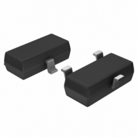
MCP1525T-I/TT Microchip Technology, MCP1525T-I/TT Datasheet - Page 3

MCP1525T-I/TT
Manufacturer Part Number
MCP1525T-I/TT
Description
IC VOLT REF 2.5V SOT23-3
Manufacturer
Microchip Technology
Datasheet
1.MCP1525T-ITT.pdf
(20 pages)
Specifications of MCP1525T-I/TT
Reference Type
Series
Package / Case
SOT-23-3, TO-236-3, Micro3™, SSD3, SST3
Voltage - Output
2.5V
Tolerance
±1%
Temperature Coefficient
50ppm/°C
Voltage - Input
2.7 ~ 5.5 V
Number Of Channels
1
Current - Quiescent
100µA
Current - Output
2mA
Operating Temperature
-40°C ~ 85°C
Mounting Type
Surface Mount
Product
Voltage References
Topology
Series References
Output Voltage
2.5 V
Initial Accuracy
1 %
Average Temperature Coefficient (typ)
50 ppm/C
Series Vref - Input Voltage (max)
7 V
Series Vref - Input Voltage (min)
2.7 V
Shunt Current (max)
8 mA (Typ)
Maximum Operating Temperature
+ 85 C
Input Voltage
5.5 V
Minimum Operating Temperature
- 40 C
Mounting Style
SMD/SMT
Series Vref - Supply Current (max)
100 uA
Lead Free Status / RoHS Status
Lead free / RoHS Compliant
Current - Cathode
-
Lead Free Status / Rohs Status
Lead free / RoHS Compliant
Other names
MCP1525T-I/TT
MCP1525T-I/TTTR
MCP1525TI/TT
MCP1525T-I/TTTR
MCP1525TI/TT
Available stocks
Company
Part Number
Manufacturer
Quantity
Price
Company:
Part Number:
MCP1525T-I/TT
Manufacturer:
LT
Quantity:
3 400
Part Number:
MCP1525T-I/TT
Manufacturer:
MICROCHIP/微芯
Quantity:
20 000
AC ELECTRICAL SPECIFICATIONS
TEMPERATURE SPECIFICATIONS
1.1
1.1.1
Output voltage is the reference voltage that is available
on the output pin (V
1.1.2
The input (operating) voltage is the range of voltage
that can be applied to the V
device produce the designated output voltage on the
V
© 2005 Microchip Technology Inc.
Electrical Characteristics: Unless otherwise indicated, T
AC Response
Bandwidth
Input and Load Capacitors (see Figure 4-1)
Input Capacitor
Load Capacitor
Noise
MCP1525 Output Noise Voltage
MCP1541 Output Noise Voltage
Note 1:
Electrical Characteristics: Unless otherwise indicated, T
Temperature Ranges
Specified Temperature Range
Operating Temperature Range
Storage Temperature Range
Thermal Package Resistances
Thermal Resistance, TO-92
Thermal Resistance, SOT-23-3
Note 1:
OUT
pin.
2:
Specification Descriptions and
Test Circuits
The input capacitor is optional; Microchip recommends using a ceramic capacitor.
These parts are tested at both 1 µF and 10 µF to ensure proper operation over this range of load capacitors. A wider
range of load capacitor values has been characterized successfully, but is not tested in production.
These voltage references operate over the Operating Temperature Range, but with reduced performance. In any case,
the internal Junction Temperature (T
OUTPUT VOLTAGE
INPUT VOLTAGE
Parameter
Parameter
OUT
).
IN
pin and still have the
Sym
Sym
BW
C
E
E
E
E
C
T
T
T
JA
JA
no
no
no
no
IN
A
A
A
L
J
) must not exceed the Absolute Maximum specification of +150°C.
Min
Min
-40
-40
-65
—
—
—
—
—
—
—
—
1
A
A
= +25°C, V
= +25°C, V
Typ
Typ
100
500
145
700
132
336
0.1
—
90
—
—
—
Max
Max
+125
+150
1.1.3
The output temperature coefficient or voltage drift is a
measure of how much the output voltage (V
vary from its initial value with changes in ambient
temperature. The value specified in the electrical
specifications is measured and equal to:
EQUATION 1-1:
+85
IN
IN
10
—
—
—
—
—
—
—
—
Where:
= 5.0V, V
= 5.0V and V
V
V
NOM
NOM
Units
Units
µV
µV
µV
µV
TCV
°C/W
°C/W
kHz
µF
µF
°C
°C
°C
P-P
P-P
P-P
P-P
SS
OUTPUT VOLTAGE DRIFT (TCV
= 2.5V, MCP1525
= 4.096V, MCP1541
OUT
= GND, I
SS
Notes 1
Notes 2
0.1 Hz to 10 Hz
10 Hz to 10 kHz
0.1 Hz to 10 Hz
10 Hz to 10 kHz
Note 1
= GND.
=
------------------------------------
V
OUT
MCP1525/41
OUT
= 0 mA and C
T
A
V
Conditions
Conditions
NOM
ppm
L
DS21653B-page 3
= 1 µF.
C
OUT
OUT
) will
)


