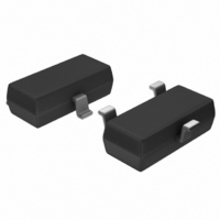
MCP1525T-I/TT Microchip Technology, MCP1525T-I/TT Datasheet - Page 4

MCP1525T-I/TT
Manufacturer Part Number
MCP1525T-I/TT
Description
IC VOLT REF 2.5V SOT23-3
Manufacturer
Microchip Technology
Datasheet
1.MCP1525T-ITT.pdf
(20 pages)
Specifications of MCP1525T-I/TT
Reference Type
Series
Package / Case
SOT-23-3, TO-236-3, Micro3™, SSD3, SST3
Voltage - Output
2.5V
Tolerance
±1%
Temperature Coefficient
50ppm/°C
Voltage - Input
2.7 ~ 5.5 V
Number Of Channels
1
Current - Quiescent
100µA
Current - Output
2mA
Operating Temperature
-40°C ~ 85°C
Mounting Type
Surface Mount
Product
Voltage References
Topology
Series References
Output Voltage
2.5 V
Initial Accuracy
1 %
Average Temperature Coefficient (typ)
50 ppm/C
Series Vref - Input Voltage (max)
7 V
Series Vref - Input Voltage (min)
2.7 V
Shunt Current (max)
8 mA (Typ)
Maximum Operating Temperature
+ 85 C
Input Voltage
5.5 V
Minimum Operating Temperature
- 40 C
Mounting Style
SMD/SMT
Series Vref - Supply Current (max)
100 uA
Lead Free Status / RoHS Status
Lead free / RoHS Compliant
Current - Cathode
-
Lead Free Status / Rohs Status
Lead free / RoHS Compliant
Other names
MCP1525T-I/TT
MCP1525T-I/TTTR
MCP1525TI/TT
MCP1525T-I/TTTR
MCP1525TI/TT
Available stocks
Company
Part Number
Manufacturer
Quantity
Price
Company:
Part Number:
MCP1525T-I/TT
Manufacturer:
LT
Quantity:
3 400
Part Number:
MCP1525T-I/TT
Manufacturer:
MICROCHIP/微芯
Quantity:
20 000
MCP1525/41
1.1.4
The dropout voltage of these devices is measured by
reducing V
Under these conditions the dropout voltage is equal to:
EQUATION 1-2:
The
temperature and load current.
In Figure 2-18, the dropout voltage is shown over a
negative and positive range of output current. For
currents above zero milliamps, the dropout voltage is
positive. In this case, the voltage reference is primarily
powered by V
milliamps, the dropout voltage is negative. As the
output current becomes more negative, the input
current (I
current begins to provide the needed power to the
voltage reference.
1.1.5
Line regulation is a measure of the change in output
voltage (V
voltage (V
measured in either µV/V or ppm. For example, a 1 µV
change in V
would net a V
1.1.6
Load regulation is a measure of the change in the
output voltage (V
output current (I
measured in mV/mA.
1.1.7
The input current (operating current) is the current that
sinks from V
put pin. This current is affected by temperature and the
output current.
1.1.8
The Input Voltage Rejection Ratio (IVRR) is a measure
of the change in output voltage versus the change in
input voltage over frequency, as shown in Figure 2-7.
The calculation used for this plot is:
EQUATION 1-3:
DS21653B-page 4
dropout
IN
IN
OUT
IN
) reduces. Under this condition, the output
DROPOUT VOLTAGE
LINE REGULATION
LOAD REGULATION ( V
INPUT CURRENT
INPUT VOLTAGE REJECTION
RATIO
). This is expressed as V
IN
OUT
to the point where the output drops by 1%.
IVRR
) as a function of a change in the input
to V
OUT
IN
V
voltage
. With output currents below zero
caused by a 500 mV change in V
OUT
DROP
OUT
SS
/ V
=
) as a function of the change in
without a load current on the out-
). Load regulation is usually
IN
20
=
of 2 µV/V, or 2 ppm.
log
is
V
IN
-------------
V
V
OUT
–
affected
IN
V
OUT
dB
OUT
OUT
by
/ V
/ I
IN
ambient
OUT
and is
)
IN
1.1.9
The long-term output stability is measured by exposing
the devices to an ambient temperature of 125°C
(Figure 2-9) while configured in the circuit shown in
Figure 1-1. In this test, all electrical specifications of the
devices are measured periodically at +25°C.
FIGURE 1-1:
Configuration.
1.1.10
The output voltage hysteresis is a measure of the
output voltage error once the powered devices are
cycled over the entire operating temperature range.
The amount of hysteresis can be quantified by
measuring the change in the +25°C output voltage after
temperature excursions from +25°C to +85°C to +25°C
and also from +25°C to -40°C to +25°C.
V
IN
V
V
V
= 5.5V
OUT
LONG-TERM OUTPUT STABILITY
SS
OUTPUT VOLTAGE HYSTERESIS
IN
MCP1525
MCP1541
C
1 µF
Dynamic Life Test
© 2005 Microchip Technology Inc.
L
R
L
±2 mA
square wave
@ 10 Hz


