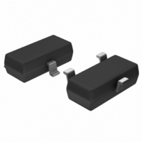
MCP1525T-I/TT Microchip Technology, MCP1525T-I/TT Datasheet - Page 5

MCP1525T-I/TT
Manufacturer Part Number
MCP1525T-I/TT
Description
IC VOLT REF 2.5V SOT23-3
Manufacturer
Microchip Technology
Datasheet
1.MCP1525T-ITT.pdf
(20 pages)
Specifications of MCP1525T-I/TT
Reference Type
Series
Package / Case
SOT-23-3, TO-236-3, Micro3™, SSD3, SST3
Voltage - Output
2.5V
Tolerance
±1%
Temperature Coefficient
50ppm/°C
Voltage - Input
2.7 ~ 5.5 V
Number Of Channels
1
Current - Quiescent
100µA
Current - Output
2mA
Operating Temperature
-40°C ~ 85°C
Mounting Type
Surface Mount
Product
Voltage References
Topology
Series References
Output Voltage
2.5 V
Initial Accuracy
1 %
Average Temperature Coefficient (typ)
50 ppm/C
Series Vref - Input Voltage (max)
7 V
Series Vref - Input Voltage (min)
2.7 V
Shunt Current (max)
8 mA (Typ)
Maximum Operating Temperature
+ 85 C
Input Voltage
5.5 V
Minimum Operating Temperature
- 40 C
Mounting Style
SMD/SMT
Series Vref - Supply Current (max)
100 uA
Lead Free Status / RoHS Status
Lead free / RoHS Compliant
Current - Cathode
-
Lead Free Status / Rohs Status
Lead free / RoHS Compliant
Other names
MCP1525T-I/TT
MCP1525T-I/TTTR
MCP1525TI/TT
MCP1525T-I/TTTR
MCP1525TI/TT
Available stocks
Company
Part Number
Manufacturer
Quantity
Price
Company:
Part Number:
MCP1525T-I/TT
Manufacturer:
LT
Quantity:
3 400
Part Number:
MCP1525T-I/TT
Manufacturer:
MICROCHIP/微芯
Quantity:
20 000
2.0
Note: Unless otherwise indicated, T
FIGURE 2-1:
Temperature.
FIGURE 2-2:
Ambient Temperature.
FIGURE 2-3:
Temperature.
© 2005 Microchip Technology Inc.
Note:
100
1.0
0.9
0.8
0.7
0.6
0.5
0.4
0.3
0.2
0.1
0.0
90
80
70
60
50
40
30
20
10
0
2.525
2.520
2.515
2.510
2.505
2.500
2.495
2.490
2.485
2.480
2.475
-50
TYPICAL PERFORMANCE CURVES
-50
MCP1525 and MCP1541
The graphs and tables provided following this note are a statistical summary based on a limited number of
samples and are provided for informational purposes only. The performance characteristics listed herein
are not tested or guaranteed. In some graphs or tables, the data presented may be outside the specified
operating range (e.g., outside specified power supply range) and therefore outside the warranted range.
-50 -25
Source Current =
0 mA to 2 mA
Sink Current =
0 mA to -2 mA
-25
MCP1525
-25
Ambient Temperature (°C)
Ambient Temperature (°C)
MCP1541
MCP1525
Ambient Temperature (°C)
0
Output Voltage vs. Ambient
Load Regulation vs.
Input Current vs. Ambient
0
0
25
25
25
50
MCP1541
75
50
A
50
= +25°C, V
100
4.140
4.130
4.120
4.110
4.100
4.090
4.080
4.070
4.060
4.050
4.040
75
75
100
100
IN
= 5.0V, V
SS
= GND, I
FIGURE 2-4:
Temperature.
FIGURE 2-5:
Frequency.
FIGURE 2-6:
Density vs. Frequency.
140
120
100
1.E+00 1.E+01 1.E+02 1.E+03 1.E+04 1.E+05 1.E+06
7
6
5
4
3
2
1
0
80
60
40
20
1,000
0
1
OUT
-50
100
MCP1525 and MCP1541
10
1
0.1
= 0 mA and C
V
10
V
IN
-25
IN
= 2.7V to 5.5V
MCP1525
MCP1525
= 4.3V to 5.5V
MCP1541
1
Ambient Temperature (°C)
100
MCP1525/41
Frequency (Hz)
Line Regulation vs. Ambient
Output Impedance vs.
Output Noise Voltage
0
I
OUT
10
Frequency (Hz)
MCP1541
L
= +2 mA
1k
= 1 µF.
25
100
10k
50
I
1k
OUT
DS21653B-page 5
= -2 mA
100k
10k
75
1M
100k
100


