GNM314R71C683MA01L Murata Electronics North America, GNM314R71C683MA01L Datasheet - Page 190
GNM314R71C683MA01L
Manufacturer Part Number
GNM314R71C683MA01L
Description
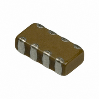
CAP 4-ARRAY 68000PF 16V X7R 1206
Manufacturer
Murata Electronics North America
Series
GNMr
Datasheet
1.GNM1M2R61A105ME14D.pdf
(221 pages)
Specifications of GNM314R71C683MA01L
Capacitance
0.068µF
Voltage - Rated
16V
Dielectric Material
Ceramic
Number Of Capacitors
4
Circuit Type
Isolated
Temperature Coefficient
X7R
Tolerance
±20%
Mounting Type
Surface Mount
Package / Case
1206 (3216 Metric)
Height
0.031" (0.80mm)
Size / Dimension
0.126" L x 0.063" W (3.20mm x 1.60mm)
Lead Free Status / RoHS Status
Lead free / RoHS Compliant
Other names
490-3444-2


!Note
• This PDF catalog is downloaded from the website of Murata Manufacturing co., ltd. Therefore, it’s specifications are subject to change or our products in it may be discontinued without advance notice. Please check with our
• This PDF catalog has only typical specifications because there is no space for detailed specifications. Therefore, please approve our product specifications or transact the approval sheet for product specifications before ordering.
sales representatives or product engineers before ordering.
!Note
No.
12 Deflection
13
14
15
16
* "Room condition" Temperature: 15 to 35D, Relative humidity: 45 to 75%, Atmospheric pressure: 86 to 106kPa
AC250V(r.m.s.) Type (Which Meet Japanese Law) Specifications and Test Methods
Continued from the preceding page.
Solderability of
Termination
Humidity
Insulation
Resistance
to Soldering
Heat
Temperature
Cycle
• Please read rating and !CAUTION (for storage, operating, rating, soldering, mounting and handling) in this catalog to prevent smoking and/or burning, etc.
• This catalog has only typical specifications because there is no space for detailed specifications. Therefore, please approve our product specifications or transact the approval sheet for product specifications before ordering.
Item
Appearance
Capacitance
Change
D.F.
I.R.
Dielectric
Strength
Appearance
Capacitance
Change
D.F.
I.R.
Dielectric
Strength
Appearance
Capacitance
Change
D.F.
I.R.
Dielectric
Strength
No marking defects
75% of the terminations are to be soldered evenly and continuously.
No marking defects
Within T15%
0.05 max.
More than 1,000M
In accordance with item No.4
No marking defects
Within T10%
0.025 max.
More than 2,000M
In accordance with item No.4
No marking defects
Within T15%
0.05 max.
More than 2,000M
In accordance with item No.4
4.5Z2.0
4.5Z3.2
5.7Z5.0
LZW
(mm)
3.5
3.5
4.5
a
d
Specifications
100
b
a
c
Fig. 2
Dimension (mm)
7.0
7.0
8.0
b
4.5
t : 1.6
2.4
3.7
5.6
c
GA2 Series Specifications and Test Methods
1.0
d
Solder the capacitor to the testing jig (glass epoxy board) shown
in Fig. 2.
Then apply a force in the direction shown in Fig. 3. The soldering
should be done using the reflow method and should be
conducted with care so that the soldering is uniform and free of
defects such as heat shock.
Immerse the capacitor in a solution of ethanol (JIS-K-8101) and
rosin (JIS-K-5902) (25% rosin in weight proportion).
Immerse in solder solution for 2T0.5 sec.
Immersing speed: 25T2.5mm/s
Temp. of solder: 245T5 C Lead Free Solder (Sn-3.0Ag-0.5Cu)
The capacitor should be subjected to 40T2D, relative humidity of
90 to 98% for 8 hrs., and then removed in room condition* for 16
hrs. until 5 cycles.
Preheat the capacitor as in table.
Immerse the capacitor in solder solution at 260T5D for 10T1
sec. Let sit at room condition* for 24T2 hrs., then measure.
#Immersing speed: 25T2.5mm/s
#Pretreatment
*Preheating
Fix the capacitor to the supporting jig (glass epoxy board) shown
in Fig. 4.
Perform the 5 cycles according to the 4 heat treatments listed in
the following table.
Let sit for 24T2 hrs. at room condition,* then measure.
#Pretreatment
Perform a heat treatment at 150
let sit for 24T2 hrs. at room condition.*
Perform a heat treatment at 150
let sit for 24T2 hrs. at room condition.*
Step
Step
1
2
1
2
3
4
Max. Operating Temp.T2
Min. Operating Temp.T3
235T5 C H60A or H63A Eutectic Solder
Glass Epoxy Board
Temperature (D)
R230
Capacitance meter
Temperature
Room Temp.
Room Temp.
100 to 120D
170 to 200D
45
Test Method
20 50
Fig. 3
Fig. 4
45
Continued on the following page.
Pressurize
Pressurizing
speed: 1.0mm/s
W
Y10
W
Y10
0
0
Flexure=1
D for 60T5 min. and then
D for 60T5 min. and then
Solder resist
Cu
(in mm)
Time (min.)
1 min.
1 min.
30T3
2 to 3
30T3
2 to 3
Time
189
C02E.pdf
10.12.20
Related parts for GNM314R71C683MA01L
Image
Part Number
Description
Manufacturer
Datasheet
Request
R

Part Number:
Description:
BUZZER PIEZO 25VP-P SMD
Manufacturer:
Murata Electronics North America

Part Number:
Description:
CAP 4-ARRAY 680PF 100V X7R 1206
Manufacturer:
Murata Electronics North America
Datasheet:
Part Number:
Description:
CAP 4-ARRAY 1000PF 100V X7R 1206
Manufacturer:
Murata Electronics North America
Datasheet:
Part Number:
Description:
CAP 4-ARRAY 1800PF 100V X7R 1206
Manufacturer:
Murata Electronics North America
Datasheet:

Part Number:
Description:
CAP CER 1000PF 50V 10% X7R 0402
Manufacturer:
Murata Electronics North America
Datasheet:
Part Number:
Description:
CAP CER 10000PF 16V 10% X7R 0402
Manufacturer:
Murata Electronics North America
Datasheet:

Part Number:
Description:
CAP 5.5-25PF 2.5X3.2MM SMD
Manufacturer:
Murata Electronics North America
Datasheet:

Part Number:
Description:
CAP 4.5-20PF 2.5X3.2MM SMD
Manufacturer:
Murata Electronics North America
Datasheet:

Part Number:
Description:
CAP 5.0-20PF 3.2X4.5MM SMD RED
Manufacturer:
Murata Electronics North America
Datasheet:

Part Number:
Description:
CAP 2.0-6.0PF 3.2X4.5MM SMD BLU
Manufacturer:
Murata Electronics North America
Datasheet:

Part Number:
Description:
CAP 1.4-3.0PF 3.2X4.5MM SMD BRN
Manufacturer:
Murata Electronics North America
Datasheet:

Part Number:
Description:
CAP 3.0-10PF 3.2X4.5MM SMD WHT
Manufacturer:
Murata Electronics North America
Datasheet:

Part Number:
Description:
CAP 2.0-6.0PF 4X4.5MM TOPADJ BLU
Manufacturer:
Murata Electronics North America
Datasheet:

Part Number:
Description:
CAP 8.5-40PF 4X4.5MM TOPADJ YEL
Manufacturer:
Murata Electronics North America
Datasheet:

Part Number:
Description:
CAP 8.0-45PF 2.5X3.2MM SMD
Manufacturer:
Murata Electronics North America
Datasheet: