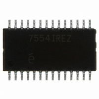
EL7554IREZ Intersil, EL7554IREZ Datasheet - Page 12

EL7554IREZ
Manufacturer Part Number
EL7554IREZ
Description
IC REG 4A DC-DC STEP DN 28HTSSOP
Manufacturer
Intersil
Type
Step-Down (Buck)r
Specifications of EL7554IREZ
Internal Switch(s)
Yes
Synchronous Rectifier
Yes
Number Of Outputs
1
Voltage - Output
0.8 ~ 6 V
Current - Output
4A
Frequency - Switching
370kHz
Voltage - Input
3 ~ 6 V
Operating Temperature
-40°C ~ 85°C
Mounting Type
Surface Mount
Package / Case
28-TSSOP Exposed Pad, 28-eTSSOP, 28-HTSSOP
Primary Input Voltage
3.3V
No. Of Outputs
1
Output Voltage
6V
Output Current
4A
No. Of Pins
28
Operating Temperature Range
-40°C To +85°C
Msl
MSL 3 - 168 Hours
Current Rating
4A
Rohs Compliant
Yes
Lead Free Status / RoHS Status
Lead free / RoHS Compliant
Power - Output
-
Available stocks
Company
Part Number
Manufacturer
Quantity
Price
Company:
Part Number:
EL7554IREZ
Manufacturer:
INTERSIL
Quantity:
2 058
Part Number:
EL7554IREZ
Manufacturer:
INTERSIL
Quantity:
20 000
Company:
Part Number:
EL7554IREZ-T13
Manufacturer:
INFINEON
Quantity:
8 623
Company:
Part Number:
EL7554IREZ-T7
Manufacturer:
Intersil
Quantity:
373
output capacitor with the ESR to satisfy the output ripple
ΔV
When output has a step load change ΔI
drop is ESR*ΔI
loop has the chance to respond. The higher the output
capacitance, the lower the voltage drop is. Also, higher loop
bandwidth will generate less voltage drop. Experiment with
the transient response (see Figure 15) to determine the final
values of output capacitance.
Like the input capacitor, it is recommended to use X5R or
X7R type of ceramic capacitors, or SPCAP or POSCAP type
of Polymer capacitors for the low ESR and high capacitance.
Generally, the AC current rating of the output capacitor is not
a concern because the RMS current is only 1/√12 of ΔI
This is easily satisfied.
LOOP COMPENSATION
Current mode converter forces the inductor current
proportional to the error signal, thus gets rid of the 2nd order
effect formed by the inductor and output capacitor. The PWM
comparator and the inductor form an equivalent
transconductance amplifier. So, a simple Type 1
compensator is good enough to generate a high bandwidth
stable converter. The compensation capacitor and resister
are decided by:
where:
• GM
• V
• I
• C
• GM
• F
ΔV
C
R
R
C
C
OUT
GM
GM
best performance, set this value to about one-tenth of the
switching frequency.
O
OUT
O
C
OUT
OUT
=
=
requirement:
=
is the intended crossover frequency of the loop. For
PWM
PWM
EA
EA
V
---------------------------------------------------------------- -
2
=
ΔI
output current
FB
×
output voltage
is output capacitance
V
--------------- -
is the transconductance of the error amplifier,
= 120µs
R
I
L
OUT
OUT
×
×
π
OUT
is the transconductance of the PWM comparator,
= 120s
GM
ESR
×
F
O
C
×
PWM
. Then V
C
--------------- -
×
C
OUT
I
OUT
C
×
GM
O
EA
will drop even further before the
12
O
, the initial voltage
L
.
EL7554
Design Example
A 5V to 1.8V converter at 4A is needed.
The input capacitor or combination of capacitors has to be
able to take about 1/2 of the output current, e.g., 2A. TDK’s
C3216X5RIA106M is rated at 2.7A, 6.3V, meeting the above
criteria using 2 generators less input voltage ripple.
ΔI
L = 2.2µH. TDK RLF7030-2R2M5R4 has the required
current rating.
L = 2.2µH yields about 0.9A inductor ripple current. 47µF
ceramic capacitor has less than 5mΩ of ESR easily
satisfying by the requirement. ESR is not the only factor
deciding the output capacitance. As discussed earlier, output
voltage droops less with more capacitance when converter is
in load transient. Multiple iterations may be needed before
final components are chosen.
50kHz is the intended crossover frequency. With the
conditions R
R
For convenience, Table 3 lists the compensation values for
frequently used output voltages.
L
1. Choose the input capacitor
2. Choose the inductor. Set the converter switching
3. Choose the output capacitor
4. Loop compensation
C
L
=
= 1A yields 1.72µH. Leave some margin and choose
= 2.32kΩ and C
frequency at 600kHz:
(
------------------------------------------- -
V
V
IN
V
IN
O
3.3
2.5
1.8
1.5
1.2
0.8
1
–
×
(V)
V
ΔI
C
O
TABLE 3. COMPENSATION VALUES
L
)
and C
×
×
F
V
S
O
C
C
= 0.018pF
are calculated as:
R
C
4.22
3.24
2.32
1.91
1.54
1.27
1.02
(kΩ)
C
November 5, 2007
0.018
0.018
0.018
0.018
0.018
0.018
0.018
C
(µF)
FN7360.5


