MIC23150-55YMT TR Micrel Inc, MIC23150-55YMT TR Datasheet - Page 10
MIC23150-55YMT TR
Manufacturer Part Number
MIC23150-55YMT TR
Description
IC REG PWM SYNC BUCK 2A 8MLF
Manufacturer
Micrel Inc
Series
HyperLight Load™r
Type
Step-Down (Buck)r
Datasheet
1.MIC23150-SYMT_TR.pdf
(15 pages)
Specifications of MIC23150-55YMT TR
Internal Switch(s)
Yes
Synchronous Rectifier
Yes
Number Of Outputs
1
Voltage - Output
1.35V
Current - Output
2A
Frequency - Switching
4MHz
Voltage - Input
2.7 ~ 5.5 V
Operating Temperature
-40°C ~ 125°C
Mounting Type
Surface Mount
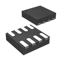
Package / Case
8-TMLF®
Lead Free Status / RoHS Status
Lead free / RoHS Compliant
Power - Output
-
Other names
576-3651-2
MIC23150-55YMT TR
MIC23150-55YMT TR


Functional Description
VIN
The input supply (VIN) provides power to the internal
MOSFETs for the switch mode regulator along with the
internal control circuitry. The VIN operating range is 2.7V
to 5.5V so an input capacitor, with a minimum voltage
rating of 6.3V, is recommended. Due to the high
switching speed, a minimum 2.2µF bypass capacitor
placed close to VIN and the power ground (PGND) pin is
required. Refer to the layout recommendations for
details.
EN
A logic high signal on the enable pin activates the output
voltage of the device. A logic low signal on the enable
pin deactivates the output and reduces supply current to
0.01µA. MIC23150 features built-in soft-start circuitry
that reduces in-rush current and prevents the output
voltage from overshooting at start up. Do not leave the
EN pin floating.
SW
The switch (SW) connects directly to one end of the
inductor and provides the current path during switching
cycles. The other end of the inductor is connected to the
load, SNS pin and output capacitor. Due to the high
speed switching on this pin, the switch node should be
routed away from sensitive nodes whenever possible.
Micrel Inc.
October 2009
10
SNS
The sense (SNS) pin is connected to the output of the
device to provide feedback to the control circuitry. The
SNS connection should be placed close to the output
capacitor. Refer to the layout recommendations for more
details.
AGND
The analog ground (AGND) is the ground path for the
biasing and control circuitry. The current loop for the
signal ground should be separate from the power ground
(PGND) loop. Refer to the layout recommendations for
more details.
PGND
The power ground pin is the ground path for the high
current in PWM mode. The current loop for the power
ground should be as small as possible and separate
from the analog ground (AGND) loop as applicable.
Refer to the layout recommendations for more details.
M9999-102309-B
MIC23150
Related parts for MIC23150-55YMT TR
Image
Part Number
Description
Manufacturer
Datasheet
Request
R

Part Number:
Description:
2.0A 4MHz HyperLight LoadT Buck Regulator
Manufacturer:
Micrel Inc
Datasheet:
Part Number:
Description:
1.5A 4MHz HyperLight LoadT Buck Regulator
Manufacturer:
Micrel Inc
Datasheet:
Part Number:
Description:
2.0A 4MHz HyperLight LoadT Buck Regulator
Manufacturer:
Micrel Inc
Datasheet:
Part Number:
Description:
2.0A 4MHz HyperLight LoadT Buck Regulator
Manufacturer:
Micrel Inc
Datasheet:

Part Number:
Description:
Manufacturer:
Micrel Inc
Datasheet:
Part Number:
Description:
Manufacturer:
Micrel Inc
Datasheet:
Part Number:
Description:
Manufacturer:
Micrel Inc
Datasheet:
Part Number:
Description:
Manufacturer:
Micrel Inc
Datasheet:
Part Number:
Description:
Manufacturer:
Micrel Inc
Datasheet:
Part Number:
Description:
Manufacturer:
Micrel Inc
Datasheet:
Part Number:
Description:
Manufacturer:
Micrel Inc
Datasheet:
Part Number:
Description:
Manufacturer:
Micrel Inc
Datasheet:
Part Number:
Description:
Manufacturer:
Micrel Inc
Datasheet:
Part Number:
Description:
Manufacturer:
Micrel Inc
Datasheet: