LTC3788IGN-1#TRPBF Linear Technology, LTC3788IGN-1#TRPBF Datasheet - Page 19
LTC3788IGN-1#TRPBF
Manufacturer Part Number
LTC3788IGN-1#TRPBF
Description
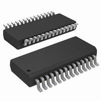
IC BOOST SYNC ADJ 25A DL 28-SSOP
Manufacturer
Linear Technology
Type
Step-Up (Boost)r
Datasheet
1.LTC3788EGN-1PBF.pdf
(30 pages)
Specifications of LTC3788IGN-1#TRPBF
Internal Switch(s)
No
Synchronous Rectifier
Yes
Number Of Outputs
2
Voltage - Output
Adj to 60V
Current - Output
25A
Frequency - Switching
105kHz ~ 760kHz
Voltage - Input
4.5 ~ 38 V
Operating Temperature
-40°C ~ 125°C
Mounting Type
Surface Mount
Package / Case
28-SSOP
Lead Free Status / RoHS Status
Lead free / RoHS Compliant
Power - Output
-
Available stocks
Company
Part Number
Manufacturer
Quantity
Price


APPLICATIONS INFORMATION
bypassing is needed to supply the high transient currents
required by the MOSFET gate drivers and to prevent in-
teraction between the channels.
High input voltage applications in which large MOSFETs
are being driven at high frequencies may cause the maxi-
mum junction temperature rating for the LTC3788-1 to be
exceeded. The INTV
gate charge current, may be supplied by either the VBIAS
LDO or the EXTV
pin is less than 4.8V, the VBIAS LDO is enabled. In this
case, power dissipation for the IC is highest and is equal
to V
on operating frequency, as discussed in the Effi ciency
Considerations section. The junction temperature can be
estimated by using the equations given in Note 3 of the
Electrical Characteristics. For example, the LTC3788-1
INTV
supply when not using the EXTV
To prevent the maximum junction temperature from being
exceeded, the input supply current must be checked while
operating in continuous conduction mode (PLLIN/MODE
= INTV
When the voltage applied to EXTV
V
EXTV
EXTV
to regulate the INTV
is less than 5.4V, the LDO is in dropout and the INTV
voltage is approximately equal to EXTV
is greater than 5.4V, up to an absolute maximum of 6V,
INTV
Signifi cant thermal gains can be realized by powering
INTV
to a 5V supply reduces the junction temperature in the
previous example from 125°C to 77°C:
If more current is required through the EXTV
is specifi ed, an external Schottky diode can be added
between the EXTV
all cases EXTV
IN
T
T
LDO is turned off and the EXTV
J
J
IN
CC
CC
CC
CC
CC
= 70°C + (15mA)(40V)(90°C/W) = 125°C
= 70°C + (15mA)(5V)(90°C/W) = 77°C
CC
• I
is regulated to 5.4V.
current is limited to less than 15mA from a 40V
LDO remains on as long as the voltage applied to
remains above 4.55V. The EXTV
from an external supply. Tying the EXTV
) at maximum V
INTVCC
CC
. The gate charge current is dependent
CC
≤ VBIAS.
CC
LDO. When the voltage on the EXTV
CC
CC
and INTV
current, which is dominated by the
voltage to 5.4V, so while EXTV
IN
.
CC
CC
CC
pins. Make sure that in
CC
supply:
rises above 4.8V, the
LDO is enabled. The
CC
CC
. When EXTV
LDO attempts
CC
LDO than
CC
pin
CC
CC
CC
CC
The following list summarizes possible connections for
EXTV
Topside MOSFET Driver Supply (C
External bootstrap capacitors C
pins supply the gate drive voltages for the topside MOSFETs.
Capacitor C
external diode D
When one of the topside MOSFETs is to be turned on, the
driver places the C
desired MOSFET. This enhances the MOSFET and turns on
the topside switch. The switch node voltage, SW, rises to
V
on, the boost voltage is above the input supply: V
V
to be 100 times that of the total input capacitance of the
topside MOSFET(s). The reverse breakdown of the external
Schottky diode must be greater than V
Fault Conditions: Overtemperature Protection
At higher temperatures, or in cases where the internal
power dissipation causes excessive self-heating on chip
(such as an INTV
shutdown circuitry will shut down the LTC3788-1. When
the junction temperature exceeds approximately 170°C,
the overtemperature circuitry disables the INTV
causing the INTV
down the entire LTC3788-1 chip. Once the junction tem-
perature drops back to approximately 155°C, the INTV
LDO turns back on. Long term overstress (T
should be avoided as it can degrade the performance or
shorten the life of the part.
IN
IN
EXTV
INTV
lator resulting in an effi ciency penalty at high input
voltages.
EXTV
nal supply is available in the 5.4V to 6V range, it may
be used to power EXTV
with the MOSFET gate drive requirements. Ensure that
EXTV
and the BOOST pin follows. With the topside MOSFET
+ V
CC
INTVCC
:
CC
CC
CC
CC
to be powered from the internal 5.4V regu-
< VBIAS.
Connected to an External Supply. If an exter-
Left Open (or Grounded). This will cause
B
. The value of the boost capacitor C
in the Block Diagram is charged though
CC
B
CC
B
from INTV
short to ground), the overtemperature
supply to collapse and effectively shut
voltage across the gate-source of the
CC
CC
providing it is compatible
B
when the SW pin is low.
connected to the BOOST
B
LTC3788-1
, D
IN(MAX)
B
)
J
.
> 125°C)
CC
B
BOOST
19
needs
LDO,
37881fa
CC
=
Related parts for LTC3788IGN-1#TRPBF
Image
Part Number
Description
Manufacturer
Datasheet
Request
R

Part Number:
Description:
IC CTLR BOOST 2PH DUAL 28SSOP
Manufacturer:
Linear Technology
Datasheet:

Part Number:
Description:
CD ROM LINEARVIEW DATASHEETS
Manufacturer:
Linear Technology

Part Number:
Description:
Standalone Linear Li-Ion Battery Charger with Thermal Regulation in ThinSOT
Manufacturer:
Linear Technology Corporation
Datasheet:
Part Number:
Description:
Low noise, high frequency, 8th order linear phase lowpass filter
Manufacturer:
Linear Technology Corporation
Datasheet:
Part Number:
Description:
Manufacturer:
Linear Technology Corporation
Datasheet:
Part Number:
Description:
Manufacturer:
Linear Technology Corporation
Datasheet:
Part Number:
Description:
Manufacturer:
Linear Technology Corporation
Datasheet:
Part Number:
Description:
Manufacturer:
Linear Technology Corporation
Datasheet:
Part Number:
Description:
Manufacturer:
Linear Technology Corporation
Datasheet:
Part Number:
Description:
Manufacturer:
Linear Technology Corporation
Datasheet:
Part Number:
Description:
Manufacturer:
Linear Technology Corporation
Datasheet:
Part Number:
Description:
Dual and Quad, JFET Input Precision High Speed Op Amps
Manufacturer:
Linear Technology Corporation
Datasheet:
Part Number:
Description:
Manufacturer:
Linear Technology Corporation
Datasheet:
Part Number:
Description:
1, 2, 6 and 8 Channel, 10-Bit Serial I/O Data Acquisition Systems
Manufacturer:
Linear Technology Corporation
Datasheet:
Part Number:
Description:
Manufacturer:
Linear Technology Corporation
Datasheet: