LICAL-DEC-MS001 Linx Technologies Inc, LICAL-DEC-MS001 Datasheet - Page 5
LICAL-DEC-MS001
Manufacturer Part Number
LICAL-DEC-MS001
Description
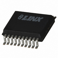
IC DECODER MS SERIES 20-SSOP
Manufacturer
Linx Technologies Inc
Series
MSr
Type
Decoderr
Datasheet
1.LICAL-DEC-MS001.pdf
(7 pages)
Specifications of LICAL-DEC-MS001
Package / Case
20-SSOP
Applications
RF, IR
Mounting Type
Surface Mount
Supply Voltage (max)
5.5 V
Supply Voltage (min)
2 V
Maximum Operating Temperature
+ 125 C
Minimum Operating Temperature
- 40 C
Mounting Style
SMD/SMT
Lead Free Status / RoHS Status
Lead free / RoHS Compliant
Lead Free Status / RoHS Status
Lead free / RoHS Compliant, Lead free / RoHS Compliant
Available stocks
Company
Part Number
Manufacturer
Quantity
Price
Company:

Part Number:
LICAL-DEC-MS001
Manufacturer:
Maxim
Quantity:
1 681


DECODER OPERATION
RECEIVE MODE
LEARN MODE
LATCH MODE
Page 8
Page 8
When the decoder first powers up, it will set the baud rate and check the state of
the RX_CNTL line. If this line is pulled high, then the decoder will go into
Receiver Control Mode. If the line is low, it will go to sleep until a rising edge (low
to high transition) on the DATA_IN line puts it into Receive Mode or a high signal
on the LEARN line puts it into Learn Mode.
When a rising edge is seen on the DATA_IN line, the decoder enters Receive
Mode. The decoder will begin by looking for a valid packet, meaning that there
are no errors and that the received Code Word matches one that is saved in
memory. If there is a match, then the decoder will reproduce the states of the
encoder’s data lines on its own data lines. It will also output the ID of the encoder
once, on reception of the first valid packet. It will then look for the next valid data
packet. If, at any time, an error or an unknown Code Word is detected, then the
decoder will ignore the packet and look for the next one.
If the timer runs out, then the decoder will go back to sleep. This time is
dependent upon the baud rate selected by the user. It is 131mS for 2,400bps and
9,600bps, and 65mS for 19,200bps and 28,800bps.
In order for the decoder to accept transmissions from an encoder, it must first
learn the encoder’s Code Word. This is done by taking the LEARN line high to
place the decoder into Learn Mode. Once in Learn Mode, the MODE_IND line
will start switching, allowing for connection of a LED to provide visual indication
that the decoder is ready to accept a new Code Word. This will continue until the
LEARN line goes high again, or until a time-out after 17 seconds.
The decoder will look for a valid transmission from an MS Series encoder. It can
store up to forty Code Words in its memory. If a new encoder is learned while the
memory is full, then the decoder will write the new word over the first word in
memory. The decoder will flash the MODE_IND line five times as an indication
that the memory is full and the next code learned will overwrite the first. The
memory will retain all of the learned Code Words if power is removed.
If the LEARN line is held high for ten seconds, then the decoder will erase all of
the stored Code Words from memory. The MODE_IND line will be high for as
long as the LEARN line is high, but after the ten seconds it will go low. Once the
LEARN line is pulled low again, the MODE_IND line will go high for two seconds
to indicate that the memory has been cleared.
The MS Series decoder has two output options based on the state of the LATCH
line. If it is low, then the data lines will be momentary, meaning that they will only
be high for as long as a valid signal is received. Once the signal stops and the
decoder times out, the lines are pulled low.
If the LATCH line is high, the decoder will pull a data line high upon reception of
a valid signal and hold it high until the signal is received a second time, at which
point the decoder will pull it low. The decoder must see a break and time out
between valid transmissions before it will toggle the outputs. The minimum
required time-out periods are listed in the Receive Mode section.
RECEIVER CONTROL MODE
TX ID
SYSTEM EXAMPLE
If the RX_CNTL line is pulled high when the decoder initially powers on, then the
decoder will enter Receiver Control Mode. Once in this mode, the RX_CNTL line
becomes an output that can be attached to the PDN or V
or a similar input on another receiver. This allows the decoder to power down the
receiver when it is not required, thereby reducing current consumption and
prolonging battery life. The decoder draws full current in this mode, but an active
receiver will typically draw much more than the decoder, so a savings is realized.
The decoder will activate the receiver for approximately one packet’s time plus
10mS for the receiver to power up, so the actual “on” time depends on the baud
rate chosen by the user. This time can be calculated in milliseconds as (60/Baud
Rate)(1000) + 10. The “off” time is nine times the “on” time, resulting in a 10%
duty cycle, greatly reducing the receiver’s current consumption. However, there
may be a lag time from when the encoder activates to when the decoder
responds. The decoder will enter Receive Mode when it sees a valid packet, so
there would only be a lag for the first packet. This can be reduced by selecting a
higher baud rate.
If this feature is not going to be used, then this pin should be tied to ground. If it
is tied to V
while trying to power down the receiver. This mode is appropriate for receivers
that have a high internal pull-up resistance, such as those offered by Linx. If the
intended receiver does not have a pull-up, then a 100kΩ or larger resistor to V
can be added to the RX_CNTL line to activate this mode.
The TX_ID line will output an eight-bit binary number to identify which learned
encoder sent the transmission. The number is output at the baud rate set by the
SEL_BAUD lines and will normally correspond to the order in which the decoder
learned the encoder, so the first encoder learned will get number ‘1’, the second
will get number ‘2’, and so on. An exception arises when the memory is full, in
which case the first numbers are overwritten as described in the Learn Mode
section. Application Note AN-00156 shows some example software to read the
TX_ID and associate it with a particular encoder. The C and Visual Basic code
is well documented so that it can be modified for a specific application.
The first step in using the decoder is to set the baud rate and determine if the
outputs should be latched or momentary. Next, the decoder will need to learn the
encoder’s Code Word. This is done by momentarily pressing the button
connected to the LEARN line. The LED connected to the MODE_IND line will
begin to flash to indicate that the decoder is ready to learn a new Code Word.
One of the buttons on the transmitter is pressed to send a signal to the decoder.
Once this is done, the LEARN button is pressed again to exit Learn Mode.
Now, when a button is pressed on the encoder, the corresponding line on the
decoder will activate. If the LATCH line is high, the data line will remain high until
the encoder button is pressed again, telling the decoder to pull the line low.
To clear the memory of the decoder, the LEARN button is pressed and held for
ten seconds, until the LED turns off. Once the button is released, the LED will
light for two seconds to indicate that the memory has been cleared.
CC
, then the decoder will create a short when it pulls the line to ground
CC
line of a Linx receiver
Page 9
CC
Related parts for LICAL-DEC-MS001
Image
Part Number
Description
Manufacturer
Datasheet
Request
R

Part Number:
Description:
IC DECODER LOW SECURITY 8DIP
Manufacturer:
Linx Technologies Inc
Datasheet:

Part Number:
Description:
IC DECODER HS SERIES 20-SSOP
Manufacturer:
Linx Technologies Inc
Datasheet:

Part Number:
Description:
IC TRANSCODER MT BI-DIR 20-SSOP
Manufacturer:
Linx Technologies Inc
Datasheet:

Part Number:
Description:
IC ENCODER LOW SECURITY 8DIP
Manufacturer:
Linx Technologies Inc
Datasheet:
Part Number:
Description:
IC ENCODER MS SERIES 20-SSOP
Manufacturer:
Linx Technologies Inc
Datasheet:
Part Number:
Description:
IC ENCODER HS SERIES 20-SSOP
Manufacturer:
Linx Technologies Inc
Datasheet:

Part Number:
Description:
Mt Series Transcoder Data Guide
Manufacturer:
Linx Technologies, Inc.
Datasheet:
Part Number:
Description:
HS SERIES ENCODER DATA GUIDE
Manufacturer:
ETC2 [List of Unclassifed Manufacturers]
Datasheet:

Part Number:
Description:
HOLDER BATTERY 20MM COIN CR2032
Manufacturer:
Linx Technologies Inc
Datasheet:

Part Number:
Description:
CONN RPSMA BL CRJA-CPV 8.5" COAX
Manufacturer:
Linx Technologies Inc

Part Number:
Description:
CABLE RG174 RPSMA M/F 8.5"
Manufacturer:
Linx Technologies Inc

Part Number:
Description:
CABLE RG174 SMA M/F 8.5"
Manufacturer:
Linx Technologies Inc

Part Number:
Description:
CABLE RPSMA/SMA 8.5"
Manufacturer:
Linx Technologies Inc

Part Number:
Description:
CABLE MALE-NMALE 8' RG-58 RPSMA
Manufacturer:
Linx Technologies Inc

Part Number:
Description:
CABLE RPSMA/SMA 8.5"
Manufacturer:
Linx Technologies Inc